
STAGES OF LAND DEVELOPMENT WORK
- Preliminary land development work process before starting work.
- Development of land during and after the construction of the building.
The preliminary development of land, e.g., cleaning, contour survey, etc. has been discussed in detail in the respective chapters.
Therefore, a list of various items minus the details are given in this chapter. shows the various types of development work required for a construction project.
DEVELOPMENT OF LAND WORK
- Developing land is important because it added to the original quality of the land and ensures an impressive and well-managed project in all respects.
- The work should be entrusted to a consultant. He can offer new concepts, better ideas, and professional advice on different developmental activities.
- The land development work process may further be divided into two parts.
- Development of structural designing companies in pune connected to the building construction.
- Development of structures and land which provide extra amenities to society.
 |
| DEVELOPMENT WORK PROCESS |
LAND DEVELOPMENT WORK PROCESS – CONNECTED BUILDING
1. COMPOUND WALL
CONSTRUCTION DETAILS OF COMPOUND WALL
- The design of the compound wall should adhere to the Architectural drawings.
- 15cm (6″) thick block work is normally used for 1.85m (6′.0″) height wall.
- If the R.C.C. column is not taken at 3.0m (10) c/c then at least block pillars of size 30cm x 30cm (12″ x 12) should be taken at a 3m interval for the stability of the compound wall.
- Blockwork should be done as per the required quality, as explained in the masonry chapter.
- Normally, plaster is not done on the blockwork. Therefore, the finishing and joints of blockwork should be of excellent quality.
- Plain concrete coping (1:2:4) should be 10cm thick over the top of the blockwork.
- Plaster the masonry R.C.C. column and top Patta (coping).
- Fix the M.S. angle in the block masonry pillars with 1:2:4 concrete.
- M.S. angle as per the drawing, of size 40 x 40 x 5mm should be used for additional security.
- M.S. angle should have a proper holdfast at the bottom and full welding at the bend.
- Make holes at about 23cm (9″) c/c for barbed wire or chain link.
- Paint the M.S. angle with red oxide. Barbed wire as per the drawing, (normally, of 2 x 12 gauge and chain-link 10 the gauge of size (5cm x 5cm) should be used.
- Tighten the barbed wire and chain link with U’ type clips.
- Cross bracing should be given for better security and enough strength.
- Cross bracing should be provided to vertical angles at corners and at an interval of 15m (50′ 0′).
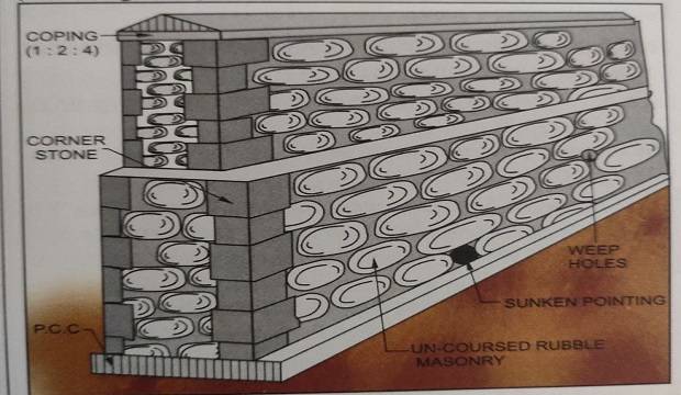
- Place A.C. pipe pieces (diameter 7.5cm or 10cm) up to ground level upper level of the ground, on either side of the retained ground for weep holes. Weep holes should be provided 1.5m (5’0″) c/c horizontally and 75cm (2’6″) vertically. in a staggered manner.
- Provide headers for uncoated rubble masonry compound wall. They should be provided at 1.5m (5’0) c/c horizontally and 75cm (2’6″) vertically, in a staggered manner.

2. RETAINING WALL
The location and the layout of the garden wall is decided by the Architect.
All the necessary drawings should be collected from the Architect for the execution of the garden wall.
Section of a garden wall as regards the foundation may vary from site to site, as per the strata available.
Following are the points to be noted while constructing a garden wall
underground water tank checklist
- The capacity of the underground water tank should be 5 times that of the overhead water tank capacity and adhere to the domestic and potable water requirements of the project.
- If a single underground water tank shall be constructed for the entire project, then it should occupy a central position.
- This position should preferably be in the central garden of the project.
- Garden (raised) can be developed on the top of U.G.W.T.
- Capacity for domestic as well as potable water can be accommodated in a circular type tank with two partitions.
- A Circular R.C.C tank is economical compared to the rectangular R.C.C tank.
- The height of U.G.W.T. should not exceed 60cm above the road level.
- Ensure Shahabad water-proofing treatment below the raft and above the P.C.C.
- Provide a sunken pit as per a requirement for the foot-valve of the pumping systems.
- Provide openings for chamber cover and suction pipe in the top slab, as per the plumbing consultant’s drawing.
- Ensure a complete box-type waterproofing from the outside of the U.G.W.T. and smooth finishing waterproofing from inside.
- The top of U.G.W.T. should be finished with smooth.
- I.P.S. water-proofing.
- Chharra plaster should be done from the outer side of U.G.W.T. over rough Shahabad, before backfilling.
- Ensure that the outer and inner compartments for domestic and potable water respectively, are watertight.
- Construct the U.G.W.T preferably in the summer, to avoid de-watering and other expenses of excavation, where water the table is at a higher level.
DEVELOPMENT WORKS PROCESS INSIDE THE BUILDING
- The flooring of parking may either be full chequered tile or partly chequered and partly rough Shahabad.
- Normally, rough shahabad of about 60cm x 60cm (2′ x 2′) or 60cm x 45cm (2′ x 1’6″) is used.
- Dressing of Shahabad should be done before fixing.
- Joints of Shahabad should match on both sides in line Dori (string) and should be finished with smooth cement and line Dori (string) marking. Shahabad should be fixed up to the outer edges of outer columns.
- Shahabad flooring should have a slope of a minimum of 75mm (3″) in every 6m (20’0″) length towards the road.
- Edges of outer Shahabad should be finished with cement mortar, to prevent cracks on the edges, due to a load of vehicles.
- Chequered tiles 25cm x 25cm (10″ x 10″) can be fixed at the entrance.
- The level of chequered tile should be slightly raised above the rough Shahabad flooring, to demarcate the walkway and parking space.
- If required, red color can be mixed in cement, for joint filling.
- Parking drawings are prepared, considering the sales requirements and allowing easy movements of the vehicles.
- Once the parking drawings are ready, they should be checked at the site practically and approval from the C.E. obtained.
- The drawing should ensure accommodation for the maximum number of cars and then two-wheelers.
- Paint markings for parking allotments as per the approved drawings.
- Paint the flat numbers on the ceiling of parking, for scooters as well as for cars.
- The minimum space required in parking for a Fiat car is 2.5m x 4.00m Maruti car – 2.25m x 3.25m and a scooter -1m x 2m.
- Provide a washing place in the parking of each building or in any other suitable place.
- The minimum size of the washing place should be 1m x 1m (3′ 3″ x 3′ 3″)
- Entry to the washing place should be from the duct and must not face the entrance of the building.
- Construct walls up to 1m (3 3″) from three sides, with a full opening from the front.
- Glazed tiles should be fixed up to 60cm (2” 0”)
- The flooring may be of LP.S., crazy mosaic flooring, or blue Tandoor.
- Nahani trap should be connected to the drainage chamber.
- One bib tap should be provided with a locking arrangement.
- The floor level of the washing place should be 10cm (4″) above the duct level.
- Provide a common toilet for servants, watchmen, and drivers, It should preferably be in the parking, with all necessary plumbing, tiling work, etc.
- To maintain and preserve the records and documents of society, the provision of office space is advisable.
- The office may be in the parking area of one of the buildings or above the underground water tank, as per the architectural drawings.
- Ensure sufficient light and ventilation in the society office.
- The cabinet should be a wooden box, fitted in a covered area.
- The size of the electrical meter cabinet depends on the number of meters to be fixed.
- About 0.3sq.m. (3s.ft.) area is required for one meter and it’s the main switch.
- The electric meter box should be fixed planned on either side of the entrance lobby.
- The depth of the meter box should be 30cm (12″). P electrical wiring in the meter box should te standard and systematic.
- The electrical cabinet should always be locked. Cit a weld mesh on the door shutters so that meter readings can be easily taken.
- Flat numbers and names of the flat owner should be marked painted on each meter.
- Paint the electric meter cabinet with oil paint.
- Provide sufficient parking lights in the parking.
- Provide a tube light in every alternate bay.
- The wiring may be battened, casing capping, or of the concealed type.
- Controls of the parking lights should be with separate D.P. in the meter box.
- Provide street lights at every corner of the building and intermediate lights along the road.
- Controls of the street lights should be with separate D.P. in the meter box.
- Provide light points on each pillar of the compound wall.
- Ensure that the design and type of light used is as per the requirement.
- Provide two separate control D.P.
- Provide alternate point control on each D.P.
- Provide and attractive sufficient illumination on the main gate.
- Controls of the compound wall lights and the main gate lights should be in the watchman’s cabin.
- Provide one light point on every landing and mid-landing.
- Provide one light point in front of the lift entrance at each landing, if applicable).-
- Controls of the staircase lights should be with separate D.P. in the meter cabinet.
- Each building should be provided with a name board for information such as flat numbers and the names of the flat holders.
- Provide wooden or metal name boards of a suitable size (normally 1.2m x 1.0m).
- Write the floor-wise numbers and names of each flat holder on the name boards.
- Fix the name boards on the left or the right side of the entrance.
- The project name is generally painted over the highest O.H.W.T of the building or front face of the building, for maximum visibility.
- On the front arch or the entrance gate of the project, ít is put up in metallic letters powder coated with approved colors painted.
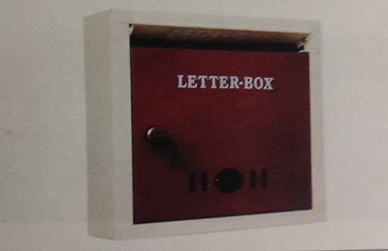
- To maintain symmetry, all letterboxes should be of the same size and design.
- They should be fixed in a suitable place in the parking.
- They should adhere to standard design and specifications.
- They should be fixed at eye level.
- Write the names of the flat owners on the letterboxes.
- Provide the flat holder’s nameplate and a flat number on the main door of each flat.
- The standard size of the nameplate is 200mm x 40mm (20 gauge).
- Standard size flat number plate 50mm (20 gauge).
- The nameplate and number plate may be of stainless steel, brass, etc.
DEVELOPMENT OF LAND WORKS PROCESS
This means to develop the surroundings of the buildings and beautifying the area.
Some common facilities can be provided.
There is a wide scope to implement new ideas and designs since there is no hard and fast rule for development neither a limit for development.
Facilities that can be provided are discussed below.
- Greenery lends natural beauty to the project. Well-planned gardens and trees enhance the aesthetics of a project. Appoint a horticulturist as a consultant. He can offer novel and creative concepts for the garden.
- Planning for trees plants along the roadside can start well in advance, (6 months to a year), so that when. the work is in progress, they will grow.
- Preferably, plant during the monsoons.
- Allow a space of 4 to 6cm between two trees.
- Trees that can remain green throughout the year should be selected for roadside plantations.
- Plants should always be a minimum of 1.2 m away from the compound wall, to prevent any damage due to the roots.
- Big trees should not be located at the turning, to avoid blindsight.
- Sprinkler system, water taps. garden entry. The lighting arrangement of the garden should be decided well in advance. Underground service, if required, should be laid well in advance.
- Precast benches should be placed below trees.
Plants suggested inside the premises and in the garden are
LAWNS
- Doob grass
- Calcutta doob grass
- Paspalum crabgrass
- American bluegrass
- Jumping grass
- Taiwan grass
Doob grass or jumping grass is very common. Decorative bushes plants should also be planted around the lawn in flower beds or along the garden wall.
The most commonly used plants bushes are
- Acalypha
- Duranta
- Lantana
- Parijatak
- Raat – Rani
- Jai – Jui
- Mogra
- Snow bush
- Powderpuff
- Hibiscus
- After planning and approval from the Archítect, Builder, and the Landscape consultant, the work of plantation should begin.
- Ensure water and pump arrangements for watering the plants.
- Take pit 60cm x 60cm (2’0 x 2’0″) at required place.
- Arrange for the garden soil and manure (khat) required for trees.
- Purchase plants in advance and keep them in a shed until actual plantation.
- Purchase plants of a bigger síze, with a growth period of about 1 to 2 years.
- Plant the selected plants in the pit without disturbing the roots and tie-up with bamboo sticks for straight growth.
- Fill the pit with garden soil and water regularly.
- Provide Tree Guards’ to protect the plants from cattle.
- Tree guards should be painted along with the nameplate.
- If the plants are outside the premises, the cover bottom portion of tree guards with gunny bags, to protect the plants from small cattle.
- Daily watering and supervision of a gardener is necessary.
- Cut the unwanted growth around the plant periodically.
- Fertilizers should be used as per the requirement.
- After the trees grow to a height of 3.0m to 4.5m (100″ to 15.0″), tree guards may be removed and used elsewhere.
Playing The equipment for the children should be provided in the garden. Some of the playing equipment and the actual playing area required is given for reference.

5. INDOOR GAMES AND RECREATION HALL
- A common hall with a stage can be utilized for society’s general body meetings, social gatherings, occasional functions, and indoor games.
- Indoor games such as cards, carom, table tennis, badminton, etc. can be accommodated in the recreation hall for the society members.
- The playing card table, carom board, and table tennis table can be accommodated on the stage area. Badminton courts can be accommodated in the area kept for audiences.
- Ensure adequate arrangements for lights, focus, etc. required for various games. The recreation hall should have separate toilets for gentlemen and ladies, a storeroom, and a changing room.
6. PRESENT TREND OF PROVISION FOR MODERN FACILITIES
- “Low budget” schemes
- “Middle class” schemes
- “High class” schemes
Under this category, the following amenities can be given
- Common dish antenna with video room
- Lawn tennis court, billiards table
- Swimming pool, waterfalls
- Health club etc.
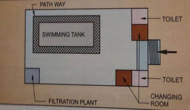
The following are the points to be considered for constructing a swimming pool
- Location with direct sunlight throughout the day.
- Shelter and privacy from all sides.
- Eàsy access for the use of heavy equipment by the contractor.
- Trees and shrubs should not dirty the pool.
- The depth of the tank should vary from shallow to deep so that trainees and experts can both enjoy swimming.
- A baby tank should also be provided for children.
- The swimming pool should be rectangular if an additional facility for water polo is to be provided. Otherwise, any geometric figure shapes can be used for the construction of the pool.
- The construction method and the specifications should be as requirements.
- The most important requirement of swimming in the pool is the filtration system, which re-circulates and filters the water.
The filtration system consists of four items
- The filters
- The pump and motor
- Vacuum cleaners
- Circulatory System
Maintenance includes water filtration by chemicals, complete cleaning of the tank by de-watering, checking and maintaining the circulating system, etc.
Maintenance of toilets, shower rooms, and changing rooms is also a part of swimming pool maintenance.
New ideas and techniques for modern amenities Include health clubs. It needs a separate building with exercise equipment for the customers. The health club may include facilities such as.
- Gymnasium hall
- Modern equipment for various exercises
- Hot and cold bath, steam bath, sauna bath, provision for body massage, etc.
- Weight loss programs, weight gain programs, etc.
- Aerobics floor
A special instructor should guide the people in the use and maintenance of the health club.
GARBAGE DISPOSAL – BUILDING
- Garbage disposal is a major concern of modern high-rise buildings because of the concentrated population. The conventional and most popular system of storage and disposal of garbage consists of the R.C.C. masonry-built garbage box (Dustbin) of an appropriate size.
- This garbage box is located on the campus. The garbage from individual units can be collected and transported up to the garbage box by wheelbarrows. The garbage is collected and carried away by the Municipal authorities regularly.
- Advanced techniques such as a ‘chute system’ can also be implemented in high-rise buildings. This system consists of installing an internal chute with automatic cleansing and disinfection units. The chute system is made of stainless steel or aluminum. Every society must implement a proper system for the garbage disposal to prevent an unhealthy environment.