The licensed person, in-charge of the electrical work, should be given the right instructions and layout plans for completing the electrical work procedure satisfactorily and safely.
It is necessary to study how the various types of loads are connected to the supply. This helps in planning the requirement of materials, tools, equipment, etc. before starting any work. In this chapter, we will discuss the different types of wiring, procedures, and requirements.
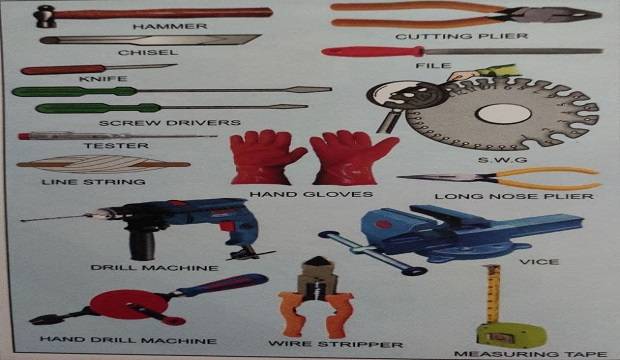
TOOLS REQUIRED FOR ELECTRICAL WORK PROCEDURE
- Screw driver set
- Wire cutting pliers set
- Hack-saw frame/blade
- Drill machine with drill bits or bit punch
- holder
- Chisel
- Hammer
- Knife
- Tester/test lamp
- Plumb bob
- Level tube
- Spirit level
- Line Dori
- Measuring tape
- Wire stripper
- Set of files
- Hand drill machine
- Die vice set
Electrical Work Cheklist Pdf Free Download Link Below
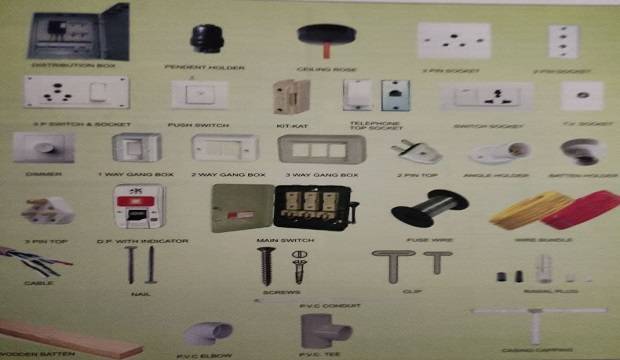
MATERIAL AND FITTINGS REQUIRED FOR ELECTRICAL WORK PROCEDURE
PLANNING OF INTERNAL ELECTRICAL WORK PROCEDURE BUILDING
Given below are a few points to be taken into consideration while planning and working.
Positions of the points depend on the requirement of individual flats. But the following points will act as a guideline while deciding their positions.
- Fan points should be diagonally in the center of the room, excluding the loft width.
- Switchboards should be nearest to the entrance, opposite the door opening.
- Switches for the bathroom should be outside the door.
- Consider the probable furniture arrangement, before deciding the switchboard and light points in the rooms.
- Powerpoint in the kitchen should be nearest to the kitchen platform. The minimum requirement of electrical points is given in the table.
NOTE: ALL WIRE SHOULD BE INSULATED INCLUDING THE EARTHING WIRE
If the electricians fix the electrical points and boards arbitrarily, it will prove inconvenient to the users. After practical studies of their requirements, some standards have been recommended for fixing the heights of various electrical points.
STANDARD HEIGHTS OF ELECTRICAL POINTS FROM FINISHED FLOOR LEVEL (F.F.L.)
3. SIZES OF BOARDS
The wooden switchboards for surface mounting are usually available in standard sizes. Normally in one two-bedroom flat, the following sizes of boards can be used, considering the minimum electrical points in each room.
| SR NO | TYPE OF BOARD | SIZE IN MM |
| 1 | DISTRIBUTION BOARD | 350MM X 305MM |
| 2 | SWITCHBOARD IN LIVING/ KITCHEN/ BEDROOM | 200MM X 250MM |
| 3 | SWITCHBOARD OUTSIDE W.C/BATH | 180MM X 100MM |
| 4 | SWITCHBOARD REFRIGERATOR IN KITCHEN 15 AMP | 155MM X 100MM |
| 5 | BELL PUSH | 100MM X 100MM |
| 6 | BRACKET LIGHT POINT AND FAN POINT | 100 MM DIAMETER |
| 7 | T.V/TELEPHONE SOCKET | 100MM X 100MM |
| 8 | T.V ELECTRICAL POINT (5 AMP) | 100MM X 100MM |
4. GAUGES OF WIRES
Electrical wires directly carry the electrical current. So, it is essential to know the current carrying capacity of the wire for safe working.
Different types and qualities of wires are designed for different purposes, as per the gauges of the wire. The weight of the wire for 100m for different gauges is given in Table.
House Wiring in Board at home
|
|

6. COLOUR CODES OF WIRES
COLOUR CODE OF WIRES ELECTRICAL WORK
| Sr No | TYPE OF SUPPLY | COLOUR OF WIRES |
| Single Phase | ||
| 1 | Phase | Red |
| 2 | Neutral | Black |
| 3 | Earthing | Green |
| Three Phase | ||
| 1 | Phase | Red |
| 2 | Phase | Yellow |
| 3 | Phase | Blue |
| 4 | Neutral | Black |
| 5 | Earthing | Green |
PLANNING FOR EXTERNAL ELECTRICAL WORK PROCEDURE BUILDING
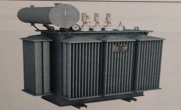
1. TRANSFORMER AND L.T. (LOW TENSION) ROOM
Loads above 50 KW require a transformer and L.T. room. The following points should be considered while planning the location of the transformer place and L.T. room.
- The location of an electrical work procedure transformer/L.T. room, for a group of buildings, should be at the nearest convenient place on the ground floor.
- The floor level of the transformer/low tension room shall be above the highest flood level in the locality.
- The availability of nearby power lines may also be kept in view while deciding the location of the transformer/low-tension room.
- In the L.T. Room, provision for cable trench, for passing cables from the transformer room should be provided.
- The plinth for the transformer should be constructed in rubble masonry, at the required height and size.
- The capacity of the transformer depends upon o the load of the building.
- The load should be calculated from the electrical points in each flat and each building.
2. FEEDER PILLAR
- The feeder pillar is a distribution box. It is generally fixed in a common convenient place. The cable from the main supply board (L.T. room) comes in the feeder pillar and is distributed to various outgoing and other points of supply.
- The feeder pillar should be fixed on a firm concrete platform.
- The feeder pillar should be painted in red and marking the building number for the feeder pillar should always be intact.
- Feeder pillars are available in 200, 400, 600, and 1000Amp capacities.
3. BUS-BAR
- Bus-bar is a distribution box that provides tappings to different electrical meters.
- The main supply to the bus-bar is provided from the feeder pillar by a suitable cable.
- Bus-bars are available in 100, 200, 400Amp capacity.
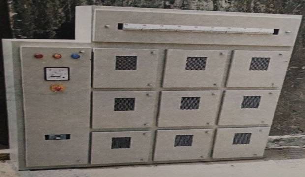
4. ELECTRICAL METER CABINET
- A meter cabinet is required to contain the meters of each building.
- Generally, the meter cabinet is made of a wooden frame, covered with wooden shutters and weld mesh. For proper ventilation, the meter cabinet should be located near the entrance of the building. This also allows easy access to the readings.
- The meter box should be fixed above 45cm (1’6″) from the floor level.
- The size of the meter box should be decided as per the number of meters to be fixed.
- For one meter about 0.28sq.m. (3s.ft.) space is required to accommodate fuse, main switch, and the meter.
- The meter cabinet should always be locked to prevent any mishaps.
- All the meters in the cabinet should display the correct name and the flat number, for easy maintenance.
- Wiring in the meter box should be safe and done properly, with the required size and color. codes of the wire.
- The building number should be painted on the bus bar, in the meter box.
- M.C.B. should be provided for every electrical meter.
- The meter cabinet should be painted with primer and oil paint to avoid decay and termite attack.
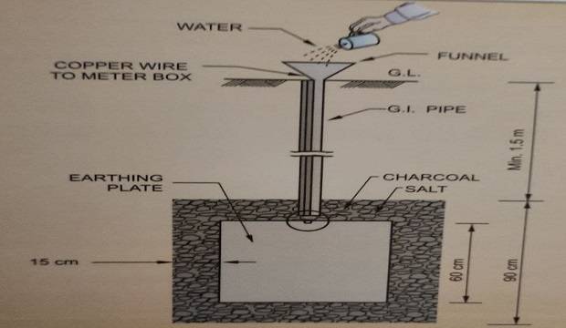
5. EARTHING PROCEDURE
- Earthing is the term used for the electrical connection to the general mass of the earth.
- There are various methods of earthing but the most common method is earthing by plate electrodes.
- Plate electrodes are made of copper or galvanized iron.
- The size of the copper plate shall not be less than 600mm x 600mm x 3.15mm and the thickness of the iron plate should not be less than 6.30mm.
- The earthing plate should be placed vertically, on its edge.
- The top edge of the plate should not be less than 1.5m below the surface of the ground.
- The resistance of the earth electrodes depends upon the resistance of the soil.
- Dig a pit of size 90 cm x 90 cm x 90 cm, 1.5 m below the ground level.
- Put a 15 cm layer of charcoal and salt to reduce the resistance of the soil.
- Tie the copper wire/galvanized iron wire to the earthing plate and put the plate in the pit.
- Size of the wire should not be less than 3 sq.mm. in case of copper wire and 6 sq.mm, in case of G.I wire. Fix a funnel from the pit to the ground level to pour water, to maintain a safe value of earth resistance. The earth resistance value should not exceed 0.7 Ohms.
- Provide another G.I. pipe of 25mm diameter to pass the earth wire up to and above ground level.
- Fill the pit (90cm x 90cm x 90cm) with charcoal and salt, 40kg each. Refill the balance pit with soil and compact it properly.
6. CABLING AND DUCTING
- Once the locations of the transformer, L.T. room, feeder pillar, meter cabinets, etc. are finalized, decide on the cabling and ducting.
- Most of the cables are laid underground in conduits.
- In case of a cable without conduits, lay it carefully. Ensure a bricklayer and sand cushion, with an excavation of a minimum of 1m depth. Generally, at road crossings, pipes are laid for protecting the cables.
- A chamber should be provided at each junction and turning. It should be covered properly, about 15cm (6″) from the ground level, to prevent mud and water from entering.
- Specimen load and cable size calculations for one building with 14 flats are given in the table.
TYPES OF WIRING USED IN BUILDING CONSTRUCTION
- Temporary wiring on the construction site.
- C.T.S. P.V.C. wiring.
- Casing capping wiring.
- Conduit wiring. It is of two types :
- Open conduit wiring
- Concealed conduit wiring
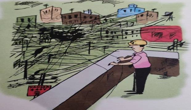
This type of wiring is employed for the temporary use of electricity supply on construction sites. Here, V.I.R. (Vulcanized India Rubber) or P.V.C. (Polyvinyl chloride) insulated wires are run through porcelain bobbins. The system is called the over headlines. Over headlines are easy to install and can be dismantled quickly after the work is over. They are also cheaper.
 |
| TEMPORARY WIRING |
- Erect wooden poles at a distance of 10m C/ C from the meter to the required location on the site.
- Fix the distribution box at a convenient place, preferably near every building, for the electricity supply to operate the different machines and fixtures.
- Run the V.I.R. or P.V.C. insulated electric wires through the porcelain bobbins on the poles. with G.I. wire for support.
- Pull the G.I. wire to prevent sagging.
- Connect this supply from the meter to the distribution box or to the required location on the site.
- Ensure that D.B. is provided near every building.
- Check all the wires for any damage in insulation before starting the supply.
 |
| Load and cable size calculation for building |
- Check the gauge and type of wire.
- Check the height of poles from the ground (approximately 4m to 5m).
- Centre-to-center distance between the poles.
- Use of G.I. wire to support wires.
- Fortnightly inspection.
- Any damage to the insulation of the wire should be covered with insulation tape.
- Ensure that all poles are properly positioned.
2. BATTEN WIRING (C.T.S. WIRING)
- Mark the line on the walls and ceiling as per the plan.
- The lines marked on the wall/ceiling should be in perfect alignment and level.
- Use a plumb bob, measuring tape, and nylon line Dori.
- Use battens of well-seasoned teak wood, not less than 12mm finished thickness.
- The width should be according to the total width of the wires laid on the batten. Apply a coat of varnish to the battens.
- Select a suitable size of the batten, for each section of wiring.
- Cut the battens, considering allowance for the joints.
- Tin clips should be fixed on the varnished wooden batten before fixing it on the ceilings or walls.
- Fix the clips on the batten, with rust-resistant nails, at a distance of 15cm in case of vertical runs and 10cm in case of horizontal runs.
- For external batten wiring work, which is exposed to sun and rain, use special clips.
- After this, fix the batten on the walls or ceiling with screws.
- Fix the screws after drilling the holes with a drilling machine and use the Rawal plug for a better grip.
- Where the batten wiring passes through walls or floors, the cables should be enclosed in conduit.
- Measure and cut the wires as per the battens on the wall.
- Allow an excess length of 15 to 20cm for termination.
- Mark the ends of wires for identification, to make connections as per the electrical work procedure diagram.
- Run the wire along with the earth wire and clip the wires to the battens progressively.
- Prepare the teak wood round blocks/square boxes as required for terminating the battens.
- Drill the holes on the teak wood boards/blocks for mounting the accessories and for passing the wire.
- Pass the wire through the holes of the teak wood board/blocks.
- Fix the accessories on the boards and blocks.
- Connect the wires to the accessories.
Start the supply and test the complete wiring work.
The major advantage of C.T.S. wiring is that it is easy to locate any faults at the time of maintenance. It is also economical and takes less time to erect.
Given below is the table for wire, batten, and clips for different numbers of wires for different sizes of batten and clips.
The size of the batten depends on the number of wires.
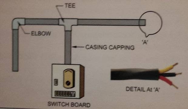
3. CASING-CAPPING
This is an open type of wiring. But compared to. the other types of open wiring, it has a better appearance, due to the cover provided over it.
PROCEDURE OF CASING-CAPPING WIRING
The procedure for this type of wiring is almost the same as explained in C.T.S. wiring, except for the points mentioned below.
- Select the width of the casing to suit the number of wires in the route.
- Insert the bunch of wires and press the capping channel.
- Fix the casing on the walls with screws, as per the lines marked.
- The screws should be at a distance of 80 to 100cm. Tie the bunch of wires to the screws.
- Insert the wires in the P.V.C. casing channel.
- Pass the wires to the other end of the casing.
- Fix the capping portion over the casing channel with the required capping accessories, at junctions and turns.
- Fix the board with accessories, using screws and grip/rawal plugs.
- Start the electricity supply.
- Check all points with the test lamp or megger.
- This wiring is expensive compared to the other types of open wiring. However, it can also be used on damp walls because water does not seep inside the casing-capping.
4. CONDUIT WIRING
There are two types of conduit wiring
- Open conduit wiring or surface wiring.
- Concealed wiring.
(a) OPEN CONDUIT WIRING
This is simple wiring. Generally, it is used in public places, c.g.., railway stations, and hospitals. schools etc. For conduit wiring work steel or P.V.C. pipes are used. For requirements of 440 volts and above, only steel conduit pipes conforming to IS 1653-1954 should be used. Open conduit wiring is easy to erect and is water-proof. P.V.C. conduits are easy to bend, cut, and shock-proof and there are no possibilities of short circuits.
MATERIAL REQUIRED
- P.V.C. or steel pipes
- Saddles (steel or P.V.C.), bend, elbows, four-way box, T, etc.
- Single P.V.C. wire
- Screws
- Wooden blocks
- Rawal plugs
PROCEDURE OF OPEN CONDUIT WIRING
- The work procedure remains the same as that of C.T.S. wiring except for the change of material and the method of fixing.
- Cut the P.V.C. pipes as per the lines marked.
- Fix the saddles as per the lines on the wall and ceiling.
- Fix only one side of the saddle on the wall. Fix the other side with screws, while laying the conduit.
- Fix the accessories serially to the conduit pipe.
- P.V.C. adhesive should be used in the conduits for joining accessories, as an additional precautionary measure in P.V.C. conducting.
- The wires should be cut according to the route and the required length.
- Ensure that an excess length of 20cm to 30cm is kept in each wire for termination.
- Insert the wires in the appropriate pipes and accessories, as per the diagram.
- Pull the wires to the other end T the pipe.
- For longer lengths of P.V.C. conduit runs, use fish wire/fish tape to pull the cables.
- Make, holes in the teak wood boxes.
- Make a hole in the wooden boxes to accommodate the P.V.C. pipes. File the edges with a filer and make a round hole. Use a half-round wood scraper filer.
- Fix the accessories to the wooden board.
- Terminate the wires in the accessories.
- Start the electricity supply.
- Test the electricity supply with a test lamp or megger.
(b) CONCEALED CONDUIT WIRING
- This type of wiring is used in residential, commercial, and public buildings for a better appearance.
- Generally, concealed P.V.C. conduits are used in place of steel conduits.
- P.V.C. conduits are economical and lighter to handle than steel conduits.
- P.V.C. conduits are resistant to acids, alkalies, oil, and moisture.
- Concealed conduits in the slab should be done before the casting of the slabs as per the electrical work procedure layout.
- In concealed wiring, fix the standard bends by bending the conduit pipe itself, to permit easy pulling of wires.
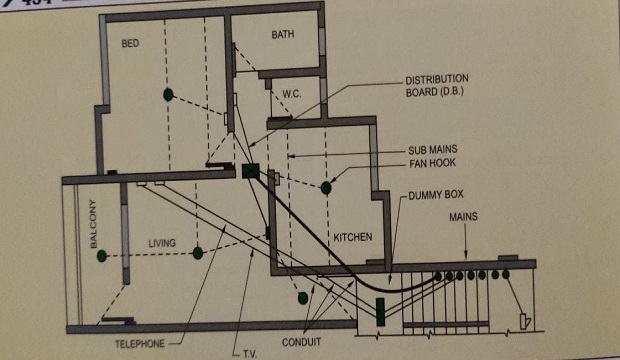
CONCEALED CONDUITS IN SLAB
- Study the electrical work procedure drawings for the positions of various points, D.B., etc.
- Fix the location of D.B. (distribution box), ensuring that it cannot be seen, while the flat is not visible from the living room.
- Provide the conduits for mains, light circuits TV, and telephone as per the approved drawings.
- Prepare the actual layout of the conducting in the slab for bill preparation and record purposes.
- Check the center of the fan hook box diagonally for center alignment, considering the loft position in the room.
- Check the locations of all the points.
- A bonding solution should be applied to all the pipes and accessories, to avoid the loose fixing of pipes with accessories.
- Tie the conduits, using binding wire, to each other, and to the slab steel.
- Provide suitable inspection boxes to permit periodical inspection and to facilitate the removal of wires, if necessary.
- Ensure that conduits do not get damaged with the movement of the laborers on the slab.
- Ensure that the fan box entries/holes are intact to prevent the cement slurry from entering.
- Before starting drop work, lay G.I. wire of 16 gauge in every conduit in the slab up to the concealed box. Keep an extra length of 15cm.
- At the time of wiring, this helps in pulling the wires.
- Drop work should commence after the completion of masonry work and a satisfactory curing period.
- Study the drawings in detail and mark the position of switch boxes with respect to the height from F.F.L.
- Do the line out on the wall by color marking.
- Start chasing of the wall with a cutting machine.
- Bends in conduit pipes should not be sharp.
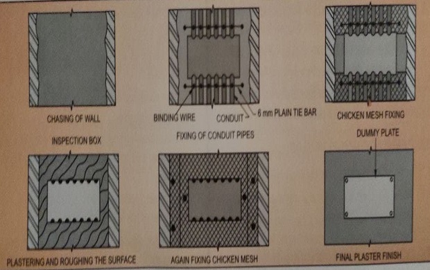
- Provide thick conduit pipes of the approved quality in the chased portion and tie them with the help of binding wires and nails.
- The conduit pipe should not project out of the It should be at least 5mm inside the wall. the surface of the wall.
- Provide an inspection box on the wall, at a suitable location.
- Fix all the boxes flush to the adjacent finished. wall, considering the thickness of the plaster.
- Finish the chased portion with cement mortar. Roughen the surface.
- In case of 3 or more conduits, provide a chicken mesh over the portion of the conduit before finishing.
- Cover all the boxes with dummy plates to prevent damage during plastering.
- Pass G.I. wires of 16 gauge. inside the conduits with an additional loop length of 15 cm.
- The same procedure should be followed for the mains and sub-mains in case of batten/casing capping wiring.
- After completion of all plastering work, clean the concealed boxes.
- After plastering and curing, wiring work can start.
- Check the quality, gauge, and brand name of the wires, as per the approvals, before starting the work.
- Check the color code and specification of the wire for various points.
- Fix the accessories on the boards, as required, with line and level.
- Terminate the wires in accessories, considering an extra length for looping.
- Put the fuse wire of the required current rating in the fuse box.
- Connect the wires in the distribution board and main switch or M.C.B.
- After starting the supply, switch on the main switch and check all the points with a megger or test lamp.
CONCEALED TELEPHONE AND TV WIRING
TELEPHONE SERVICES
- Normally, the telephone department undertakes the house wiring for telephone subscribers in small buildings. But in multi-storeyed/
- commercial buildings, wiring for telephone connections is concealed through the conduits at the time of construction.
- Calculate the total connections in the building on each floor.
- Before plastering, provide pipes in the wall, through the staircase as required, and give floor-wise connections from the main junction box on the ground floor.
- Provide underground pipes from the main junction box in the building to the mainline of the telephone authorities.
- Fix inspection boxes on every floor for maintenance purposes.
- After plastering work, wiring is done in every flat/office/shop from the main junction box on the ground floor.
- Mark or tag every wire, shop-wise and flat-wise, to identify the wire at the time of connection.
 |
| flow chart concealed wiring |
COMMON ANTENNA SYSTEM FOR TELEVISION (C.A.T.V.)
- In multi-storeyed apartments, buildings, houses, and hotels where many TV receivers are located, a common master antenna system may be used to avoid mushrooming of individual antennae.
- Generally, the master antenna is provided at the topmost point of the building.
- A suitable room on the terrace or below the waist slab of the staircase should be provided for the amplifier and video unit, in consultation with the Architect Consultant.
- From the amplifier/video room, conduits are laid up to individual flats.
- Suitable “Tap-Off” boxes may be provided in every room/flat as required.
- Provide one direct 5Amp. plug point without an on-off switch in the video/amplifier room.
- The common video room shall be located in the geometrically central building on the premises.
- TV/Telephone conducting work should be carried out to ensure an easy and convenient maintenance routine.
- Proper identification signs/stickers should be provided on all TV and telephone boxes in the staircase.
- Sizes of the conduits should be selected to accommodate the required number of wires running through them.
- Provide 10cm x 10cm x 5cm M.S. box for TV and telephone in the living room of the flat.
- Provide independent 5Amp. plug point near TV socket for electrical connection to the TV.
- Provide the required size of boxes in the staircase for TV and telephone, separately.
- All conducting procedure is the same as the electrical concealed conduits in the slab and wall.
CHECKLIST FOR ELECTRICAL WORK BUILDING
- Check the number of points in each room as per the drawing.
- Check the location of the points.
- Ensure that the height of all the boards and points is as specified.
- Check the line, level, and alignment of battening / casing-capping.
- Ensure that the quality and specification of all the material is as approved.
- Check the sizes of the boards as per the pictures on it.
- Check the internal connections inboard for phase and neutral distribution.
- Check the color codes and sizes of the wire used for various points.
- Check the operation of all the switches for smooth working.
- Ensure that there is no gap between the batten and the wall.
- Ensure that rust-proof clips are fixed.
- Check the quality and tightening of all the screws with required spacing and with proper gripers Rawal plugs.
- Check the earthing connections for effective working.
- Check the supply for all the points by megger or test lamp and prepare the final testing report.
- Check all the points in the staircase.
- Check the wiring in the meter cabinet for quality, color codes of wires, a gauge of wire, switches, connections in bus bar, etc.
- Ensure that the name of the flat owner is painted on the respective meter and the main switch.
- Check the sizes of cables for the required capacity.
- Check the main supply for sufficient voltage.
- Check the parking, street lighting, and all common supply.
TESTING OF ELECTRICAL WIRING WORK BUILDING
There are several tests to check the electrical wiring work. The following tools and equipment are required for testing of the wiring installation.
- Combination plier
- Screwdriver
- Neon tester
- Electricians knife
- Calibrated rheostat 0 10 Ohms, 20 Amps
- Ammeter 0 – 20 Amp e
- Battery 6 volts
- Moving coil voltmeter 0 10V
- Megger 1000V
- Earth tester/earth megger
- Mains should be switched off.
- Determine the rating of the fuse.
- Replace the main fuse wire of the known rating.
- Check the rating of the fuse in each circuit.
- Label the respective fuse in the D.B. circuit using stickers.
This test is carried out to verify that all the single-pole switches have been fitted in the same wire throughout and such wire has been connected to the live wire of the supply.
With the circuit-switched ‘ON’, one can check whether all switches are on the live site or not.
- Disconnect all the apparatus and put all switches in the ‘ON’ position with their covers removed.
- Connect one side of the test lamp to ‘neutral’.
- Touch the other lead of the test lamp to the terminals of each switch.
- If the switch is connected to the live wire, the test lamp will light up.
 |
| Detail fuse electric box |
3. TESTING FOR EFFECTIVENESS OF EARTH CONTINUITY
This test is carried out to check whether the earth connection from the installation to the main earth electrode is effective.
- For this test, a direct reading Ohm-meter and a battery are used.
- Connect one lead to the earth terminal and the other to the farthest part of the installation.
- Touch one testing leads to the terminal of the metal body of the D.B. and the other leads to the phase terminal.
- If the test lamp glows with normal brightness it indicates that the continuity in earth electrode resistance is reasonably good.
 |
| Testing equipment electric work |
4. INSULATION TEST
From this test, one can find the insulation resistance between the cable of the installation and the earth. From the insulation resistance value, one can calculate the leakage current.
- First, switch off the main switch and remove the fuses from the main switch.
- Ensure that all the fuses in D.B. are of the proper rating.
- Fix all the lamps in the holders.
- Switch on the switch.
- Use an insulation tester/megger of 1000V rating.
- Join the two contacts L and N on the installation side of the main switch and connect the shortest link to terminal L’ of the megger.
- Connect the earth terminal of the main switch to one lead marked E’ of the megger.
- Disconnect all domestic appliances from the socket and short the socket before testing with the megger.
- Rotate the handle of the megger at 160 r.pm. and note the reading of the megger.
- The Insulation resistance (megger value) should be above 250 Mega-Ohms.
SINGLE PHASE SUPPLY
- A single-phase supply is normally used for appliances that need a voltage of 220 to 250 V, for example, light, fans. TV, video, etc.
- The voltage of a single phase from the supply authority is 240V.
- In single-phase, there are three wires
- Red color wire indicates phase wire.
- Black color wire indicates neutral wire.
- Green color wire indicates earth wire.
THREE-PHASE SUPPLY
- The supply authority supplies a three-phase supply with four wires i.e. three wires of phase and one wire of neutral.
- The fifth wire of the earth is taken from the earthing pit to the consumer’s place.
- The standard voltage at which the electricity board delivers power to the consumer is generally 415 V, 50HZ.
- The neutral wire is usually at zero voltage.
- The voltage between any two phases, in a three-phase system, is double (i.e. 440 V, the voltage between any phase wire and the neutral.
- The three phases are equally distributed to various rooms.
- Normally, the color code for a three-phase supply should be
- Red, yellow, and blue for phases.
- Black for neutral.
- Green for earthing.
PROTECTION SAFETY OF ELECTRICAL WORK
- Protection against earth fault.
- Protection against overload.
- Protection against short circuits.
1. PROTECTION SAFETY AGAINST EARTH FAULT CAUSES
When phase wire comes in contact with earth wire, a short circuit occurs. This happens because the neutral at the point of supply is earthed. If one of the phase wires touches the earth, a return path is provided to the current.
REMEDY
- Fuses M.C.B. shall be provided to interrupt this current due to a short circuit.
- Earth leakage circuit breaker (E.L.C.B.) shall be used to interrupt the current due to a short circuit.
2. PROTECTION SAFETY AGAINST OVERLOAD CAUSES
- Any value of current through a wire beyond the rated value that causes damage to the insulation is called overload.
- The rated current for a wire is that value of the current which does not cause the temperature of the wire to reach a value that would damage
- the insulation.
- The current carrying capacity of the wiring should not be exceeded.
- The proper design of any electrical installation is a must.
- The design of the electrical work procedure installation should be according to the expected load.
- If the switching load is more than the designed wiring load, it causes overload.
- Mechanical faults (i.e. bearing, jamming of rotors) in the motor can cause overload.
- A short circuit also causes overload.
- Designed rating fuses shall be provided to interrupt overload.
- M.C.B. shall be provided to interrupt the overload.
3. PROTECTION SAFETY AGAINST SHORT CIRCUIT
- When phase wire and neutral wire make direct contact, the excess current will flow in the circuit and cause a short circuit.
- Fuses or M.C.B. should be used to prevent short circuits.
INTRODUCTION TO PROTECTIVE INSTRUMENTS
- They are manufactured for current ratings up to 200Amp, in the medium-voltage range. M.C.B. should be used above 220Amp.
- They are better than switch fuse units for controlling lighting circuits.
- Time is not lost in fuse replacements.
- The rating of the circuit breaker should be 20% – 30% more than the rated current of the circuit, to take care of the starting current.
- It is a piece of thin metal wire that connects the circuit in which it is inserted.
- When the current through the fuse exceeds a certain value for a sufficient period, it melts.
- The part which actually melts and opens the circuit is known as the fuse element/fuse wire.
- Fuse wire details
- For geyser: 15 Amp
- For Mixer fridge: 5 Amp
- For rooms (5 to 7 points): 5 Amp
- For independent plug: 2 Amp
- Service voltage and other particulars.
- The number of poles i.e. single, double, or three poles.
- Normal current rating.
- Mounting i.e. floor or panel mounted.
- Indoor or outdoor type.
PROTECTION SAFETY OF BUILDING FROM LIGHTNING
Practically, every structure has a chance of being struck by lightning.
The degree of this probability varies depending on a number of associated factors, such as lightning incidences, surroundings, and the type of terrain.
- The type of construction of the structure largely influences the extent of protection. A steel-framed building is self-protecting to an extent and may not require any additional protection.
- Brick buildings require a greater degree of lightning protection.
- In closely built towns and cities, the hazard is not as great as in the open country.
- In the hilly or mountainous areas, a building is more susceptible to damage, than a building in plains and flat terrain.
- The height of the structure is an important factor for lightning protection. Taller structures are subject to greater hazards than smaller structures.
- Provide lightning-rod to protect buildings from lightning.
 |
| Prevention of lighting |
- Install a copper pipe of 25mm diameter (16 gauge) with a copper ball head of 60mm diameter.
- The copper ball head should have 6 Nos. of spikes.
- The length of the copper pipe should be 1.25m and it should be installed at the highest point of the building, over a gunmetal base plate, mounted on a 60cm x 60cm x 60cm angle framing box.
- A copper strip of 25 x 3mm with one end connected to the copper rod and the other end .connected to earthing should be provided.
- Separate earthing should be provided for lightning-rod.
Very good, it explains the electrical technicians work. we can now question them on the quality of their work. thanks