
1. Types of elevators are
- Passenger elevator
- Freight elevator
- Hospital elevator
- Dumb elevator
- Capsule elevator
- Usually, passenger elevators are used in building construction. For residential buildings, a passenger elevator of 5 to 8-person capacity, with collapsible or swing door shutter and single-speed is used.
- In commercial buildings elevators of 5 to 20 person capacity, automatic doors, with single double high speed is used.
- As per the rules and regulations of the Corporations, an elevator is a must for buildings with G+5 floors.
- A typical plan and elevation of the passenger elevator are shown in the figure.
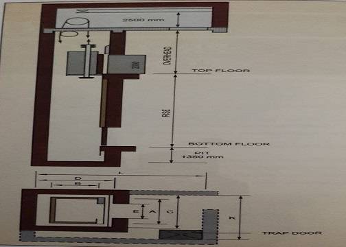
2. LIFT PIT AND MACHINE ROOM SIZES
ELEVATOR (LIFT) WORK PROCEDURES – INSTALLATION
Refer elevator (lift) work procedure drawings before the execution of any work.
Elevator Working Principle ppt Pdf Free Download Link Below
1. CIVIL WORK FOR ELEVATOR LIFT PIT
- All hoistway walls should be minimum 23cm. brick or 150mm R.C.C.
- Centre-opening doors are recommended.
- Depth should be 1.40m (4’6″) below the lowest landing level.
- The lift pit should be taken to hard strata of the ground. If the clear depth from the top of the (bottom) raft up to . the lowest landing level is more than 1.40m (4’6″), then extra depth should be filled with plum concrete.
- The lift pit should be completely watertight and rough Shahabad box-type water-proofing treatment should be provided.
- M.S. ladder should be provided for access to the lift pit.
- Provide 40cm x 40cm x 75cm, 1:2:4, concrete block in the lift pit at a place shown in the elevator drawing, to carry buffer spring vastu house.
2. CIVIL WORK FOR LIFT WELL
- Scaffolding should be provided for lift erection in the shaft and should be removed after the erection work is complete. The horizontal supports of scaffolding should be 0.90m to 1.05m (3’0″ to 3’6″) and should exceed 1.05m (3’6″).
- Provide pockets for the inside and backside walls, at the locations shown by the erection agency. Grout the same after fixing the rag bolts for the guide rails. Alternately, the guide rails can also be fixed with fasteners at these locations. This is an easier but time-consuming and expensive procedure.
- It cannot be adopted where the lift pit is more than 1.7m x 1.40m (5’6″ x 4’6″) size and requires bracket supports for guide rails.
- The fasteners or rag bolts should be provided at a distance not exceeding 2.1m (7’0″). (Confirmation from the elevator (lift) work procedure agency is required).
- To make the guide rails sturdy, they should be fixed on the concrete surface and NOT on the block brick masonry works. For this, the vertical distances between two R.C.C. bracer beams should not exceed 2.1m (7’O”).
- Make pockets and grout them for rails, brackets, indicators, boxes, etc. in position.
- During construction, provide 4 Nos. 10cm x 10cm (4″ x 4″) pockets in R.C.C. Pardi blocks brick masonry the wall at 90cm (3’0″) below the machine room bottom slab, for fixing supports of the template.
- C.P. teak wood template should be provided. The erection agency will fix up the template and plumb. The door positions can be fixed accordingly.
- For door frame designs on the ground floor and upper floors. Refer to Figure Nos. 35.2 and 35,3. Provide door frames in C.P. teak wood only.
- In the case of brick block masonry, all R.C.C. beams (in lift well) should be marked with red oil paint. 15cm (6″) stripes on all three sides (top and bottom of the beam). This helps in locating the R.C.C. beam position. The rag bolt fasteners can be fixed accordingly in the R.C.C. portion.
- The block masonry for the adjoining frames should be done with 15cm (6″) wide blocks, to prevent any chipping later on and for avoiding offset in finished plaster tiles.
- The door frames and the adjoining masonry work should be done for all floors, except for the first entry floor, i.e. either the parking or ground floor. The door frame should be erected after lift car erection and completion of all works of the entrance hall passage.
- For the landing flooring near the entrance door of the lift, consider the sill of the collapsible gate after fixing of the collapsible gate.
- Two coats of whitewash to be provided for all the walls of the lift well.
3. ELECTRICAL WORK
Three-phase a separate electric meter is required for an individual lift.
Step 2: CABLES
- 4.0mm2 x 3.5 core copper armored cable or (equivalent capacity aluminum cable) to be provided from the meter room at G.F. to the machine room.
- 2.5mm2 x 3 core copper unarmoured cable to be provided from meter room to machine room. and again to the bottom of the lift well.
Step 3: MAIN SWITCHES
2 Nos. 32 Amp capacity 1.C.T.P. (Iron-Clad Triple Pole) one in the meter room of the ground floor and the other in the machine room. 3 Nos. 16 Amps D.P., one in the meter room of the ground floor and 2 in the machine room should be provided.
Step 4: LIGHT POINTS
- One tube light point in the machine room with an additional socket and switch. One external point at the entrance door e machine room.
- In the lift well, one wooden block containing a bulb with a switch and an 8-pin socket with switch, at the level of one and a half feet below each floor level, except for the ground the floor should be provided, In addition, a similar block at the machine room floor level and one on 0.9m (3’0″) below F.F.L. at the ground floor should be provided.
Step 5: EARTHING
8 Gauge copper double earthing from the earth pit to the machine room, 1.C.T.P. motor, and the controller should be provided.
LOCATIONS
- The underground cable should run from the ground floor meter to the lift well, Inside the lift well. cables should run on the back side wall, near an of the corner of the lift, up to the location of the main switches in the machine room adjoining these cables. The lighting point should also be provided inside the lift well.
- Saddling of the cables at 0,6m (2’0″) intervals in succession should be provided.
4. ERECTION WORK
Erection of all the machines as per the P.W.D. rules and regulations should be carried out by an authorized agency.
CHECKLIST OF ELEVATOR (LIFT) WORK PROCEDURE
- Check the size of the lift pit as per the standard dimensions, specified by the manufacturer’s requirements.
- Check lift shaft for perfect right angles, plumb from top to bottom.
- Check the position, size, line, level, and plumb of lift door frames.
- Check the depth of the lift pit from parking F.F.L., as per the manufacturer’s requirements.
- Check the quality of the wood and the correct design, as per the drawing for the door frame.
- Ensure that the door frame is flush to the plaster inside the lift shaft.
- Ensure that the bottom slab of the machine room, with all openings, is as per the manufacturer. (The requirements manufacturer should be present at the time of slab casting).
- Check the hooks in the top slab, required to set the pulley at the time of erection.
- Lift machine room flooring should be of I.P.S. Check the rigidity of the foundation concrete and the bolts provided to the lift machine.
- Ensure that the opening for the trap door is closed properly with a good quality trap door.
- Ensure that the finishing of the pockets, in the lift machine room slab, is done properly.
- Ensure that landing flooring is done, considering the clear required height of the opening, in the door frame.
- The landing slope should be given away from the lift door.
- Check the rigidity of the scaffolding during erection, to prevent any accidents.
- Scaffolding should be done as per the requirement of the lift erectors.
- Check the rigidity of the rails fixed with fasteners.
- Check the alignment of the rail for truly in plumb.
- Check the quality and size of the foundation concrete for buffer springs.”
- Check all the materials supplied by the manufacturer for the required size, specification, quality, effective working, etc.
- Check the quality of workmanship for all erection work.
- Check the finishing of the lift car from the inside. Check the electricity supply with a separate electric meter for the lift.
- Check the safety arrangements during the operation of the lift like opening, auto-locking of the door, etc.
- Ensure that a sufficient counterweight is provided.
- Check the quality and specification of the electrical cables used for the lift work.
- Check the lift for smooth operation and floor-to-floor stop control, from inside and outside.
- Check all the workings of all indicators.
- Ensure sufficient ventilation in the lift machine room and a weld mesh to act as a guard from birds etc.
- Check the functioning of the earthing systems.
- Check the key for emergency operation of the lift Ensure that the instruction plate is fixed.
 |
| Typical door frame detail for collapsible door |
- A single authorized agency should handle the work, right from the start to the completion, of erecting the machines.
- For electrical and installation work, appoint agencies with authorized licenses, as per the rules laid down by the. inspectors.
- Ensure that there is no water seepage in the lift pit, machine room, and hoistway.
MAINTENANCE OF ELEVATORS (LIFT)
Maintenance of elevator (lift) work procedure should be entrusted to the authorized licensees. The agency will inspect the said works every 3 months and will attend to all the calls, as and when required.
- Lubrication of wire ropes and guide rails.
- Checking the level of machine pits.
- Motor greasing.
- Cleaning of all the equipment.
- Adjustment in electrical circuits, landing gate lock, and car gate switch.
- Inspection of hoistway switches.
LEGAL FORMALITIES OF ELEVATORS (LIFT)
‘A’ FORM
‘B’ FORM
‘C’ FORM
After obtaining both A & B permissions, apply for the ‘C’ form, i.e., permission for using the lift. The P.W.D. department will issue a license for the same.
Also, Read This.