Last updated on January 22nd, 2024 at 04:34 pm
In this chapter, we will study the planning of plumbing and sanitation works, basic norms for designing these systems, necessity, and use of plumbing drawings, requirements of plumbing work agency, tools required, specifications of various materials, the role of plumbing consultant, etc.
We will also deal with the water supply system, drainage system, mode of measurements, usage, and maintenance of plumbing and drainage work.
BASIC REQUIREMENTS OF PLANNING PLUMBING, AND SANITATION
The type of plumbing systems used for drainage are
- Single stack or double stack system.
- Types and specifications of material being used, e.g., whether C.I. or P.V.C. pipes for drainage and whether C.I./P.V.C./A.C. pipes for stormwater stacks.
- Provisions of underground tanks and overhead tanks with their prescribed capacities.
- A separate pumping system for supplying municipal drinking water to the kitchen directly.
- The necessity of fire fighting systems based on statutory provisions.
Select the water source to be used.
- Is sufficient municipal drinking water available?
- Is there any other source of water on-site, e.g. open well, tube well, etc.?
- Is the available water potable? If not, can it be made potable with some treatment methods?
- Finalize the sewage disposal system.
- Is the municipal sewer line available for the project? At what invert level?
- Is the septic tank required? Decide on the location for the septic tank.
- Engage a consultant for ‘plumbing and sanitation work procedure‘ to prepare the drawings and details, in advance. This should be done at the beginning of the project.
- Finalize the agency for the plumbing work.
BASICS OF PLUMBING SYSTEM
The plumbing system includes.
- Water supply.
- Soil pipes and fixtures.
- The sanitary drainage system, to carry the wastewater from the plumbing fixtures to the public or private disposal system.
- Stormwater drainage system to collect and carry rainwater.
- Fire fighting systems for high-rise buildings as per the statutory provisions. (All buildings may not need this)
PLUMBING AND SANITATION NORMS
An adequate quantity of clean and potable water for drinking purposes should be supplied. Water from other sources should also be made available for daily use, for twenty-four hours of efficient flushing.
Proper pumping systems with adequate stand-by arrangements should be made.
Water should be supplied with the required pressure, up to O.H.W.T. (Over Head Water Tank), and then to the individual residential units with the minimum prescribed pressure.
The system should invoke minimum maintenance.

- Smoothly finished for uninterrupted flow.
- Located in well-ventilated enclosures ducts.
- Easily accessible for the intended use and repairs.
- Able to withstand designed pressure.
- Connected to a drainage system with water seal traps.
Tested for leakages, defects, etc.
- The plumbing pipes should be
- Made of durable material and connected by suitable and satisfactory joints of good workmanship, for satisfactory service during its reasonable life expectancy.
- Easily accessible for inspection, working, and repairs.
- Made rodent-proof (e.g., rat, mouse, squirrel, etc.)
- Tested for leakages, defects, etc.
3. SANITARY AND DRAINAGE SYSTEMS
- It should be well-designed, executed, operated, and maintained according to national standards. And as per the provisions of the local municipal authority.
- It should be leak-proof while crossing the potable water supply system.
- Should be properly ventilated and have an adequate trap system, provided with necessary water seals to avoid foul gases.
- It should have properly prescribed slopes.
- It should require minimum water for proper performance and cleaning.

4. STORMWATER DRAINAGE
- All building terraces should have proper slopes for carrying rainwater towards a catch point.
- The total project should be well planned to avoid the accumulation of ‘rainwater in ducts, parking, on roads, or on open grounds.
- We should have well-connected stormwater drains with proper slopes for carrying unused water. These drains should be inspected and maintained properly, especially before rains.
5. USE OF PLUMBING DRAWINGS
- Plumbing drawings must include all the minor details. These drawings prove useful as mentioned below –
- Drawings are useful for calculating the accurate quantity of the materials to be used.
- For procuring good materials as per I.S. Specifications.
- To avoid unnecessary wastage of the materials.
- To coordinate all the steps of plumbing work.
- To plan and execute the work properly.
- Proves easy maintenance of underground and concealed pipes.
- To provide appropriate accessories for reducing frictional losses.
REQUIREMENTS OF PLUMBING WORK AGENCY (PLUMBING WORK CONTRACTOR)
1. BASIC QUALIFICATION OF PLUMBING WORK CONTRACTOR
- A plumbing works license is issued on application to individuals as follows
- To a civil engineering graduate or diploma holder,
- To non-technical persons (provided the following eligibility criteria are satisfied) –
- Minimum qualification->SSC.
- Minimum Age->21 years.
- Reference->Certificate of the work done, from two architectural or contracting agencies.
- The examination is conducted by the local government authorities. After passing this examination, the license is issued.
- The license is valid for a fixed period and needs to be renewed.
2. RULES AND RESPONSIBILITIES OF THE PLUMBING CONTRACTOR
To execute the plumbing work, a good contractor should follow the guidelines given below
- Should prepare/help in preparing the working drawings and get them approved by the local authorities.
- Should study the detailed drawings, regarding the plumbing works of the project.
- Should visualize any practical difficulties in carrying out the work as shown and to make the necessary changes, during the initial planning stage.
- Should follow up with the plumbing consultant for preparing proposals of water and drainage systems and necessary approvals.
- We should employ a team of skilled plumbers and skilled workers to ensure good workmanship for the project.
- The contractor should assist the plumbing work consultant in obtaining the necessary N.O.C (No Objection Certificate) approvals etc. after the completion of the works.
- I should be able to attend to any complaints about the completed projects and routine maintenance for the same.
3. EXPECTED WORKMANSHIP FROM THE PLUMBING CONTRACTOR
- A good plumbing contractor should know all the prevailing rules and complete the works accordingly.
- Should employ experienced plumbers to execute the job, to ensure quality work and prevent any maintenance problems in the future.
- All practical difficulties should be discussed with the site in charge and the plumbing consultant. This minimizes the repetition of jobs and therefore, any additional overhead expenditures.
- Proper tools should be used to execute the required work.
- The contractor, as well as his workers, should have a sound knowledge of material quality and specifications, to prevent any mistakes.
- The plumbing contractor should not hamper spoil other works like plastering. waterproofing. tiling, electrical conducting, etc. He should take the necessary precautions for improving the workmanship of the total project and not of plumbing work alone.
A good plumbing contractor should give proper weightage to safety precautions during the progress of works. The following steps should be observed.
- All work activities should be done in a systematic manner and phase-wise.
- All external work should be done, using proper scaffolding. While using ropes zulas, sufficient care should be taken to prevent accidents.
- All work should be done with the proper tools. Worn-out and old tools require more manpower and may lead to accidents.
- Coordination with other work agencies is a must. This also helps to maintain the safety of the workers employed by the other contractors.
- A good contractor should maintain a first-aid box on the site, in case of accidental injuries.
- During trenching work, the prescribed safety rules should be followed.
5. COORDINATION WITH OTHER AGENCIES
INTRODUCTION
Plumbing work of the building requires coordination with other activities, to ensure smooth working. Excellent building construction is impossible without good teamwork and for good teamwork, coordination of all the agencies is essential.
ADVANTAGES OF CO-ORDINATION
Excellent coordination results in quality construction and benefits everyone concerned. The flat fetches a good resale value for its owner and earns a good reputation for the builder and engineers.
Teamwork and coordination result in minimizing defects, less manpower, and avoiding duplication of the work.
TYPES OF AGENCIES INVOLVED
- Waterproofing agency
- Masonry & Plaster agency
- Tiling agency
- Electrical agency
- Painting agency
- Departmental agency
PRE-WORK
Sunken floor should be plastered with C.M. 1:4 with a water-proofing compound and tested for water tightness.
The first coat of water-proofing should be done before fixing sanitary traps, in case of water closets (W.C.) and toilets.
The first coat of water-proofing and brickbat Coba coat should be done before fixing the bends of rainwater lines at the terrace level.

POST WORK
- Sanitary traps and waste pipes of wash hand basins (W.H.B.) should be well embedded in the brickbat coba coat.
- The final finishing coat should be carried out for the toilet and terrace after the curing of the brickbat coba coat.
- Curing should be done for 14 days.
NECESSARY PRECAUTIONS
All the trap joints should be properly finished to avoid any leakage problems in the future.
In the case of terrace rainwater pipes, the joint near the bend should be neatly finished with cement mortar, to prevent leakages.
Masonry Plasterwork agencies are closely related to plumbing, as all vertical G.I., C.I., P.V.C. lines run on plastered surfaces. Concealed lines are always hidden in the masonry, hence coordination between plumbing and masonry plaster agency is very important.
PRE-WORK
Generally, all outlets are fixed and taken out from the building face, or sleeves are provided before the external plaster, Traps should be well embedded in cement mortar at the junction.
The walls of the W.C. and bathroom should be strong enough for the chasing of grooves for concealed pipes. Masonry of these walls must be done with the correctly specified cement-sand-mortar mix with R.C.C. bands, per meter (height).
POST WORK
After concealing the pipes, grooves should be finished with the specified cement-sand-mortar and the surface should be roughened.
After fixing vertical C.I./P.V.C./G.I. lines, all holes should be plastered with rich cement-sand mortar to prevent any leakages in the future.
NECESSARY PRECAUTIONS
The duct plaster should not be ignored for its quality, plumb, line, and level.
- The plaster over which the vertical pipelines are to be run must be in line and plumb. This point should not be overlooked by the site engineer contractors.
- Improper plastering can cause problems in the plumbing lines later on, like leakage through the joints, cracking of the C.I. fittings, etc.
- Hence duct plaster must be done in perfect plumb, line, and level. engineers contractors.
CO-ORDINATION AND ROLE OF TILING AGENCY
Tiling and plumbing works are inter-linked. The following are the pre-work and post-work procedures for tiling work, with respect to plumbing work.
PRE-WORK
Generally, tiling is done after laying of plumbing pipes. So, there is hardly any pre-work as far as tiling is concerned.
POST WORK
All the concealed pipes should be properly placed and tested before fixing the glazed tile dado of the toilet.
Washbasin outlets and all the traps should be laid before the bathroom flooring work.
NECESSARY PRECAUTIONS
During polishing, the tile polisher generally sweeps the “polished tile powder slurry” in the nahani trap & I.W.C.
- This causes the pipes to choke up and may lead to repairing/replacing the pipes. To prevent this, the tile powder slurry should be collected and disposed of manually. In addition, the following points should be observed-
- The opening of I.W.C. should be filled with sand, gunny bags, and the top layer should be covered with a thick layer of P.O.P.
- Nahani trap hole should be made in the flooring tile after the completion of the polishing work.
CO-ORDINATION AND ROLE OF ELECTRIFICATION AGENCY
- Choke up problem of the plumbing lines occurs due to negligence of other agencies.
- Plumbers themselves should exercise precautions, since handling all agencies at a time is difficult.
- Plumbers should seal all the traps with gunny bags and a layer of plaster of Paris at the top, to minimize the choke-up problem.
- Remove these seals at the time of testing.
- The site engineer must supervise these activities, to avoid any problems.
TOOLS REQUIRED FOR PLUMBING AND SANITATION WORKS PROCEDURE
- Following is the list of tools used for plumbing work.
- Plumber’s hammers, tape, flat plier, gas plier, plumber’s vice, bench vice, chain wrench, pipe wrench, footprint wrench, hacksaw frame with a blade, files, chisels, caulking tools, double-ended spanner set, ring spanner set, extension bar, socket wrench various handles, various sizes die, thapi, ghamela, etc.

LIST OF MAJOR MATERIALS FOR VARIOUS PLUMBING AND SANITATION WORKS
Materials required for plumbing and sanitation work procedure can be broadly divided into two categories viz. material required for internal plumbing and sanitation work and material required for external plumbing and drainage work. All the materials should have adhered to the IS standards.
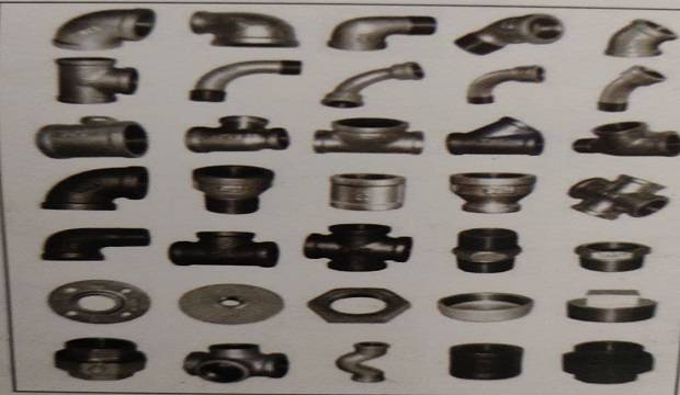
GALVANIZED IRON (G.I.) MATERIALS.
G.I. Pipes and fittings are available in various sizes i.e. 15mm, 20mm, 25mm, 32mm, 40mm, etc.
G.I. Pipes, elbows, tees, unions, sockets, plugs, stop cocks, bends, double nipples, gate valves, etc. reducers of various sizes, tag, habak, hold tite.
CAST IRON (C.I.) MATERIALS
- C.I. Pipes
- Single double sockets
- Single socket/double socket connectors
- Plain plug tees
- Plain plug bends
- Single double ‘Y’ in the length of 300 to 450mm
- Nahani traps and in diameters of 75, 100, 150mm
- C.I. chamber covers
- C.I. gully trap covers
- C.I. rainwater (R/W) shoes
- C.I. offsets
- Cowls
- R.C.C. Hume pipes NP1, NP2, NP3, NP4 grade
- Gully traps – 100mm, 150mm
- Sewer traps 150mm, 250mm
- Chamber covers – square, round, and angular
- Stoneware glazed (S.W.G.) pipes
- Rainwater pipes – 100, 150, 200mm
- Packing rope (Rassi)
- Wash hand basin (W.H.B.)
- Indian water closet (I.W.C.)
- European water closet (E.W.C.)
- Anglo-Indian water closet (A.I.W.C.)
- Bidet
- Urinals, sinks, soap dishes, etc.
SANITARY FITTINGS
(P.V.C.) MATERIALS
- Pipes Single socket Double socket
- Plain bends, plug bends
- P.V.C. plain tees, P.V.C. plug tees
- P.V.C. single ‘Y’, P.V.C. double, ‘Y’
- P.V.C. collars
- P.V.C. cowls
- P.V.C. shoes
- P.V.C. offsets, P.V.C. sockets, etc.
QUALITY CHECKING OF MATERIALS PLUMBING
1. G.I. PIPES
- Nominal diameter available in the market 15mm, 20mm, 25mm, 32mm, 40mm, 50mm, 65mm, 80mm, 100mm, 125mm, 150mm and 200mm.
- The class of pipes indicates the use.
- Wall thickness of various classes of different.
2. G.I. FITTINGS
Diameter, make threading, visible cracks, etc.
 |
| g i pipe identification |
3. VALVES
Type, size, cracks, defects, leakages, etc.
4. C.P. FITTINGS
Type, surface finish, leakages, threading, etc.
5. TRAP
Type, material, size, internal smoothness, any visible cracks, etc.
6. SANITARY FITTINGS
Type, material, size, any visible cracks, finishing, color, etc.
7. NAHANI TRAP
Material, size, length, water seal depth, weight, internal smoothness, cracks, etc.
8. P-TRAP, S-TRAP
Material, size, water seal depth, length, shape, finishing, etc.
9. C.I. PIPES
C.I. pipes should be checked for type, class length, thickness of the wall, straightness, ISI, Non-ISI, visible cracks, bends, etc.
The type of C.I. pipes ordered depends on its utilization. Soil pipe for W.C. and toilet lines, while ordinary pipes are used for bath and rainwater downtake.
Domestic water supply is provided through LA Class C.I. pipe, which comes in two classes A and B.
10. C.I. FITTINGS
The thickness of the wall, internal smoothness, correct included angles, visible cracks, brand, etc.

ROLE AND RESPONSIBILITIES OF PLUMBING CONSULTANT
The plumbing consultant for a project should be a civil engineer, holding a license to carry out plumbing work. He should possess actual field experience with a sound knowledge of plumbing and sanitation work procedures.
1. Responsibilities of the Plumbing consultant
- The consultant should be associated with the project from the planning stage.
- To coordinate the different stages of the plumbing work of an ongoing construction project.
- To provide the drawing details, considering local authority rules and regulations, regarding water supply systems, internal piping, details of all plumbing and sanitary fittings, general drainage disposal layout, stormwater drainage details, boosting system details, etc.
- To finalize levels of the proposed roads and buildings, in order to provide proper slopes for drainage.
- To propose and obtain sanctions from the Municipal authorities for the plumbing and sanitation work procedure systems.
- To collect N.O.C. from the concerned authorities for the completed work.
- To maintain quality control on works during execution.
- To issue certificates for quality of workmanship after testing and checking of G.I. lines at the required pressure, at every stage, and C.I., P.V.C., and other lines for line, level plumb, and leakages.
- To propose solutions for modifications alteration/additions/deletion in the work periodically, as per site conditions.
- To prepare the final record drawing as per the actual work execution at the site.
- specify and advise about the quality of materials to be used.
- The advice in the selection of the plumbing contractor.
- Regular site visits during the execution of the work until the completion of the project.
- Introduction of new concepts and systems as per the latest development in the plumbing field at National and International levels. The consultant should preferably be a member of the Association of Consulting Engineers (India).
- Stormwater drawing
- Drainage drawing
- Water supply lines
- Septic tank
- O.H.W.T.
- U.G.W.T.
- Terrace level distribution
- Internal plumbing work details
- Any specific details required
- Pump details
- Pump room arrangement details
- Any other structure required to carry plumbing systems
- Swimming pool (if provided), details regarding plumbing requirements/filtration plant
- plumbing details
Sewage treatment plants, if required
3. ALL DRAWINGS SHOULD HAVE THE FOLLOWING DETAILS
- Layout drawings with the levels of roads and buildings, indicating the general final contour.
- Details of total drainage disposal systems on the layout.
- Position of septic tanks, U.G. water tanks, open wells, tube wells, etc.
- Stormwater flow pattern on the layout.
- Boosting system details for various buildings.
GENERAL DRAWINGS
Individual bath W.C. toilet kitchen details.
- In plan
- In section
- Heights of various C.P. fittings, G.I. fittings
- from F.F.L.
- Specifications of all materials to be used
- Slope provision of the terrace.
- Location of rainwater outlets.
- Location of the overhead water tank.
- Detailed drawings of outlet and distribution, a network of G.I. pipes on the terrace.
- Size and capacity of the water tank.
- Inlet, outlet, washout positions, and details.
- Outlet down takes pipe details.
- Floor-wise and flat-wise distribution details.
Drainage Disposal details
- Detailed drawings of septic tank internal works.
- Inlet and outlet details.
- Necessary filter media details.
Stormwater drainage work drawings
- Necessary slopes of roads with R.L.s.
- Outlet details of rainwater pipe.
- Sectional details of the stormwater drain.
- Constructional details regarding plumbing fittings.
- Inlet, outlet, and storage capacity details.
- Necessary fittings details.
WATER SUPPLY SYSTEMS AND IT’S WORK PROCEDURE
1. INTRODUCTION
Providing water in residential premises for requirements such as drinking, cooking, washing, and cleaning is the main object of a water supply system.
Water should be,
- Free from disease-causing organisms like bacteria, viruses, etc.
- Free of undesirable taste and odour.
- Clear and colorless.
- Free of excessive minerals.
- Free of poisonous materials.
In nature, we get water as,
- Surface water in the form of rivers, lakes, and reservoirs.
- Underground water in the form of open wells and tube wells.
2. SOURCES OF WATER SUPPLY
- Municipal Corporation/Local Authority
- Bore-well at site
- Open well-at site
- Water from these sources should be tested for standard requirements of potable water. Normally, the Municipal water is supposed to be potable and no separate tests are required for it.
- The standard requirements of potable water are attached, as a test report.
SPECIMEN TEST REPORT OF WATER FROM BORE-WELL WELL
DISINFECTION OF WATER
The water received from the Municipal Corporation is treated at a central plant and disinfected. Periodical checking can be carried out to check the percentage of chlorine.
3. UNDERGROUND WATER TANK (U.G.W.T.)
- Keep U.G.W.T. @ 60cm above the finished formation level of the surrounding land.
- The capacity should be 1.5 times of O.H.W.T.
- It can be either of R.C.C. or masonry structure.
- Refer a detailed sketch for reinforcement in the R.C.C. chapter.
- Keep the bottom slab of the underground water tank, above the groundwater table and above the outlet level of the septic tank. U.G.W.T.
- should be located away from the septic tank.
- After finalizing both top and bottom slab levels, the size (length and width) can be finalized as per the required capacity, i.e., 1.5 times the capacity of O.H.W.T.
- A freeboard of a minimum of 15cm should be provided.
CONSTRUCTION PROCEDURE FOR UNDERGROUND WATER TANK
- The bottom slab should be on hard strata.
- Use a concrete mix of grade M20.
- A proper compartment should be made to store
- Municipal water and bore-well water separately.
- The water-proofing of both the compartments should be done thoroughly, before actual use.
 |
| test report bore well |
- A sunk portion of size 30 x 30 x 15cm should be kept in the bottom slab of both the compartments, for the foot valve of the pump, which also helps in cleaning of U.G.W.T.
- After completion of R.C.C. work, external plastering should be done using a proper admixture to make the tank waterproof.
- All necessary openings for inlet, overflow, pump suction pipe, and manhole cover should be executed as per the drawing.
- Installation of the pump should be done on foundation bolts, which are embedded in a firm R.C.C. foundation on the top slab. Pumps can also, be located near the side walls.
- Arrangement for a permanent M.S. ladder should be made if the depth of U.G.W.T. exceeds 2.5m.
- All necessary fabrication and welding work should be completed before the commencement of the water-proofing work.
- A room constructed on the U.G. Tank can serve as the site office during the initial stages. Later, it can be converted into a pump room/society office, etc.
4. DISTRIBUTION SYSTEMS FROM U.G. TANK TO O.H. WATER TANK
Storage water will be supplied to the O.H. tank, using pumping systems.
 |
| distribution from ugmt to ohwt
|
PLUMBING WORK
As per the distribution network and the number of O.H. tanks for water storage, the pump size and delivery pipe details will be decided.
The following points should be considered.
- The delivery pipe coming out of the pump room should be taken below ground and then to individual buildings.
- The pipe used should be of ‘C’ class and precautions should be taken to avoid leakages, due to faulty connections, etc. All bends used for the connections should belong bends, so as to minimize the frictional losses.
- G.I. tees are provided to take out the branches from the mainline near each building.
- All necessary care should be taken to fix the line in a straight line and plumb. It should be properly clamped.
- The inlet to O.H. Tank should be provided considering the proper freeboard in the tank.
- Ball cock arrangement should be provided at inlet to stop the flow of incoming water when it reaches the freeboard level.
- A separate gate valve should be provided at about 0.9m (3′) which can be used to prevent the water from going to that particular O.H. tank on the same main line.
- A suitable pump controlling system should be used as per the requirements of the project.
PUMP DETAILS
Usually, the pressure from the service mains is not sufficient to take the water up to O.H.W.T. So, the service main connection is provided into a U.G.W.T.
The water is then pumped to O.H.W.T., from where it is supplied to the individual unit by gravity, through a network of pipes and valves. Refer figure for water supply network.
- Single-phase
- Three-phase
- Positive suction pumps
- Negative suction pumps
- Self-priming pumps
- Pumps where priming is required
- Submersible
- pumps.
- Jet pumps
- Turbine pumps
- Reciprocating pumps etc.

WHAT IS PRIMING?
The pump cannot operate if the air is present in the suction pipe. “Removing the air from the suction pipe, by pouring the water in, is called priming”.
If priming is not done, the pump will run dry (DRY RUN CONDITION), and thus winding will be burned. To avoid this ‘PRIMING IS A MUST’.
- A tee is provided just above the suction pipe, through which water is poured in.
- A convenient way of priming is to tap the vertical feeding line from the pump to the O.H. tank by a lesser diameter G.I. line & connecting it to the suction line by means of a tee. A gate valve is provided to operate such a secondary line.
PROCEDURE OF PRIMING
The plug should be removed and the water poured in, with the help of a bucket jug until it overflows. The plug is fitted again and the pump is operated.
For other types of priming, before starting the pump operation, the gate valve is operated such that the water held up in the vertical feeding line flows down up to the foot valve and fills up the suction pipe. Then the pump can be operated.
5. WATER METERS
- Water meters measure the flow of water from a mainline to the house service connection. The domestic water meter should confirm to IS 779:1978.
- Domestic water meters are usually the horizontal flow type.
- Normal sizes are : 15,20,40 and 50mm.
- Selection, installation, and maintenance, should confirm to IS 2401:1973.
- A filter is fitted on the upstream (inlet side) of the water meter.
- Any air passing through the water meter will give inaccurate readings.
- Non-return valves should be provided on it’s downstream (outlet side).
- Water meters are placed in a meter box at a higher level, to avoid flooding during rains.
- Domestic water meter testing should be as per IS 6784:1984.
- The domestic water meter box should be as per IS 2104:1981.
6. BOOSTING SYSTEM AND ELECTRONIC PUMP CONTROLLER
Multi-storeyed buildings have a problem of insufficient pressure in the drinking water supply system. To overcome this problem, store water in U.G.W.T. and pump for some time. This pump is connected directly to the potable water supply pipeline network, provided to all the units. This is called the BOOSTING SYSTEM. To operate this regularly for a fixed period, an electronic pump controller can be fixed to the system.
- A separate boosting pump.
- Deciding it’s operation time, depending on the consumer’s convenience.
- A preferable automatic ON-OFF mechanism, to eliminate dependency on watchman in this critical period.
- The tail end of the drinking water pipeline network should be let in either U.G.W.T. or O.H.W.T. In case the intermediate outlets are not opened, this system helps to release the excess water pressure developed on the pipeline, that can load the pump itself.
ELECTRONIC PUMP CONTROLLER
An electronic pump controller is used to maintain a regular water supply, which may be affected.
- Irregularity of the watchman operator.
- Irregular water supply from Municipal Corporation.
- Critical electricity conditions like melting of wires due to overheating of the pump, single phasing reverse rotation, etc. which cannot be handled by the watchman.
- Spillage of water from U.G.W.T. or O.H.W.T. There are two types
- of the pump controller.
- Float type.
- Conducting type.
Points to be considered for O.H.W.T.
- O.H.W.T. is usually rectangular in shape because of design constraints. Unlike the U.G.W.T., the length and breadth of an O.H.W.T. have less flexibility, so the capacity is adjusted by varying the height.
- The capacity can be worked out by assuming the water requirement as 135 liters person per day.
- For a one-bedroom flat, five persons and for two-bedroom flat seven persons can be assumed.
- To place the inlet, outlet, and wash out pipes in position, the provision should be made while centering, by providing the necessary holes and placing the pipes of G.I. pipes (with holdfast welded.
- An opening of size 60cm x 90cm is provided in O.H.W.T. top slab for a manhole cover.
- Gate valves for each outlet, i.e., bath/W.C. line and kitchen line should be provided on the terrace parapet, for easy maintenance or replacement.
- The minimum freeboard should be 150mm.
- The overflow should be provided 25mm to 50mm below the inlet. The size should be a little larger than the inlet pipe.
- Outlets should be 10cm to 15cm above the finished bottom of the tank.
- Washout should be in flush with the finished floor and plugged properly when not in operation.
- The pipeline from the O.H.W.T. to individual units should have a minimum length of run and bends (turns).
- Gate valve for each outlet should be provided, at a height of 3.0m from the finished terrace level, for easy maintenance of the lines.
- A gate valve provided to the water line at the entry of each flat facilitates the maintenance of individual flat without affecting the water supply to other flats.
- All joints should be checked for any leakages with pressure testing equipment.
- Determine the location from where the lines are to be taken.
- Mark the plumb line for vertical stacks to be fixed on the wall.
- Erect the scaffolding without making any holes in the walls. Take vertical support from the windows inside and tie it properly.
- Fix the pipes on the wall with clips and G.I. nails of 40mm length.
- Clipping should be done at a spacing of 1.5m to 2m.
- All the holes (Chabad) should be filled with brick/block pieces and should be finished with rich cement mortar to match the wall surface.
- Do not remove the scaffolding unless all the holes are properly finished.
8. INTERNAL PLUMBING SYSTEMS
- Plaster the internal walls of bath toilets.
- Mark the line on walls with chalk, in proper
- alignment and plumb, as per the recommended heights and internal plumbing drawings.
- Start chasing the well using chisel and hammer. The chasing should be done keeping the following points in mind.
- Depth: should not exceed the pipe size.
- Width: should be sufficient to accommodate the pipeline.
- Alignment: should be done considering the straightness.
- Height: should be as per the specifications for all the fittings.
- For columns and other R.C.C. work, chasing should be strictly avoided.
- Check the class specifications of materials. Preferably ‘C’ class G.I. pipe should be used.
- Fittings should be checked for their correctness. cracks etc.
- Prepare the pipe-skeleton and check all the joints for tightness.
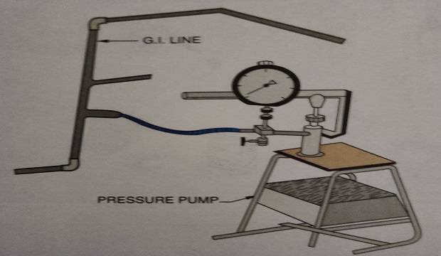
- The water tightness of the line can be checked using pressure testing equipment. All other openings should be plugged except the end portions to which the pressure gauge machine is connected.
- The pressure reading should be between 5 to 10kg/sq.cm. and even a single drop of water should not escape the joints during testing.
- Apply coal-tar over this skeleton with a brush.
- Cover this skeleton, including fittings, with a Hessian cloth (kiltan) and tie it properly.
- Fix the skeleton on the wall using 40mm plumbing nails, at a distance of 23cm (9″) on alternate sides.
- Plaster the line with cement-sand mortar. For the portion where glazed tile dado is proposed, the plaster surface should be roughened. The other portion should be properly finished with Neeru.
- Curing should be done over the ghabadi for at least seven days.
All pipe joints should be properly clamped to the wall using the required size of the clamps. For clamping, drill holes and insert wooden plug inside.
Pressure testing should be done as per the concealed line.
Open G.1. pipes should be painted with oil paint during the finishing stages, to prevent any rusting of the line.
TYPICAL PLUMBING LAYOUT FOR BATH W.C. W.H.B. KITCHEN TOILETS
- It is a fitting used to connect two pipes.
- It is used.
- At the beginning of a pipe system inside a room.
- The various fittings in plumbing works should be provided at heights as mentioned below
- For all appliances.
- Mid-way between long pipeline.
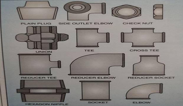
- Union enables repairs replacement of the pipeline system, without disturbing the other parts of the system.
SOCKET
These fittings are used to connect one length to another, for the continuation of the pipeline.
ELBOW
It connects two pipes at 90° and has a short curvature.
BEND
It connects two pipes at any required angle. It cannot be used in walls because of a larger curvature.
TEE
It is a fitting with a side outlet at 90° to the run of the pipe.
CROSS TEE
It is fitting with four branches arranged in pairs, each at right angles to the other.
REDUCER
This fitting is larger at one end than the other. It is used to connect pipes of two different diameters by,
- Reducer tee
- Reducer elbow
- Reducer bend
- Reducer socket
It is a piece of pipe threaded at both ends and can be used for a short extension of the plumbing line.
DOUBLE NIPPLE
It is used to connect two fittings within a short distance, It has threads on both sides of the central piece.
PLUG
It has an exterior pipe thread end and a projecting head for fitting in the socket.
CLAMPS
They are used for tightening the pipes to the walls for vertical and horizontal lines. They are available in various sizes as per the size of the pipes.
PLUMBING NAILS
Usually, plumbing nails of size 50mm and 75mm (2″ and 3″) are used and can be hammered on clamps over R.C.C. surface or brick/block masonry.
AIR VALVE
When water mains are in an undulating position, they should be provided with air outlet valves at the highest point. These valves release the air trapped in the mains when the intensity of water flow is being changed. this valve consists of a floating ball which allows the air to escape, but is set back by pressure when comes in contact with the water.
PUSH TAP
In order to prevent undue wastage of water in factories, schools, and similar buildings, self-closing taps are often used. they are particularly used for washbasins and equipment used for drinking water purposes. Generally, it is a bib tap with a horizontal inlet.
SLUICE VALVE
It controls the flow of water from the source to the town or area where water distribution is to be done. These are fixed at intervals of about 3 to 5km, to divide the pipeline in different sections. these valves are also fixed on distribution pipes. They are normally controlled by a wheel.
PILLAR TAP
It has a vertical inlet’ and is provided on washbasins. It is either bent down at 90 degrees or at an angle called the angular pillar tap.
10. FIRE FIGHTING SYSTEM
If the height of the building exceeds 15.0m, the fire fighting system must be installed in the building as per the Municipal corporation rules Details of requirements, work procedure, etc. is discussed in.
11. CHECKLIST OF PLUMBING WORK
- Are all fixtures like bib taps, mixers, etc. fixed properly?
- Is there any leakage from taps/other C.P. fixtures?
- Is there proper pressure to all the taps/cocks?
- Is the half-turn flush cock operation proper?
- Is there any choke-up in W.C., after the continuous flow of water from half-turn flush cock for at least five minutes?
- Is there any cement lump observed in the P-trap of W.C.?
- Is there any choke-up in the Nahanni trap of the bathroom, after the continuous flow of water for five minutes?
- Is the hot and cold water mixer operation proper?
- Are the boiler connections on loft properly plugged?
- Is the low-level water tank operatiòn of E.W.C. proper?
- Is the seat cover of E.W.C. fixed properly?
- Are all sanitary fixtures properly cleaned?
- Are the brackets of W.H.B. painted with oil paint?
- Are the open G.I. pipe fitting connected to E.W.C. painted?
- Is the wash hand basin fitted properly? Does it move?
- Are there any cracks/breakage to any of the sanitary fittings?
- Is there any leakage from the C.I. lines in the duct, after continuous water flow for fifteen minutes?
- Is the fixing of G.I./C.I./A.C. lines in plumb and clamped properly?
- Is there any leakage in the drainage chambers?
- Is there any leakage in the main inlet and outlet G.I. lines of the water tanks?
- Are there any cracks on white cement-filled between washbasin and wall?
- Are P.V.C. outlets pipes for wash hand basin and kitchen sink fixed properly?
- Is there any separate mark for Municipal water tap and tap from O.H.W.T.?
- Are escape spouts from W.C. and bath are provided?
Even when a plumbing contractor holding a license is appointed for a particular project, the actual work is often executed by untrained plumbers. This leads to faults in the actual work and these faults lead to major plumbing hazards at a later stage.
Generally, the following types of negligence are observed.
- Not differentiating between the various class of pipes like A, B, C, and it’s usages for a particular The work. Identification in a class of G.I. pipe is overlooked.
- Random pipe cutting practice: The cutting plane and should be perpendicular to the length of the pipeline and proper cutting farma should be used.
- Random thread practice: If threading is done to an insufficient depth and length, then wear and tear occurs, creating difficulties in maintenance.
- Using improper fittings:
- Use of low-quality or discarded fittings with hairline cracks or other problems.
- Using oversized or undersized fittings and pipes, due to non-availability of proper size.
- Insufficient use of hemp rope (tag) and hold tite for fittings.
- During concealed work, coal tar is applied carelessly, and covering kiltan on pipes is not done properly.
- Using worn-out tools can spoil the plumbing material and fittings.
- Improper chasing made on walls/columns. without due care for structural stability.
- Faulty ghabadi finishing creates problems in tiling and can cause leakages if the ghabadi work is done by a plumber or semi-skilled mason. Always employ a skilled mason for plumbing work.
- No curing arrangements are made for ghabadi finishing.
- The aspect of future maintenance work is neglected, i.e., the use of unions, gate valves, etc, is seldom done.
- No plugging is done for open points, blocked by cement mortar, during construction.”
- Unnecessary tightening of joint work/fitting connection.
- Insufficient knowledge of Municipal standards and regulations.
- Improper coordinating with other contractors viz. civil works contractor, water-proofing contractor, etc.
- The plumber may damage the waterproofing on the terrace for G.I. outlets> this can lead to leakages.
- If the waterproofing in the bath and W.C. is damaged, it can again lead to leakages.
13. POINTS NORMALLY OVERLOOKED BY THE ENGINEER
The site Civil engineer should observe the following rules.
- Always insist on plumbers with licenses and skilled workmen at the site.
- Check all plumbing materials for quality. The class of G.I. pipes should be checked, by color coding and also by sample weighing.
- Insist that proper tools be used by the plumber at the site.
- Plan all requirements properly, so as to avoid using the available fittings and pipes instead of the proper materials.
- Never rely on the requirements/sizes specified by the plumber.
- Insist on detailed plumbing drawings, along with quantity estimation by the consultant, before the commencement of any work.
- Ensure minimum wastage while cutting of full-length pipes. Even small pieces of lengths up to 15cm (6″) can be used as barrel nipples, double nipples with proper threading.
- The engineer shall have sufficient knowledge of the stacking and handling of the plumbing material. Any mishandling by the unskilled plumbers should be checked immediately and such personnel should be removed from the work.
- Even if the plumbing system is concealed, always insist on the proper alignment and verticality of pipelines.
- Pressure checking for leakages in plumbing lines is a must. It should be supervised personally and the use of the proper pressure gauge equipment should be ensured.
- Ensure sufficient knowledge of Municipal standards and regulations.
- Arrange plumbing work in coordination with other contractors. This prevents mistakes, delays, repetition of work, etc.
- Insist on the employment of skilled mason by the plumbing contractor. Never allow plumber’s helpers to do ghabadi finishing work.
- Insist on proper curing for plumbing ghabadi.
- Do not succumb to the pressure tactics of the plumbing contractor.
- Ensure that due care is being taken for other ongoing works by plumbers.
- Insist on good plumbers during progressive nib stages of the work.
- Check the top level of the Nahanni trap before water-proofing work.
- Apply kiltan cover and coal-tar to all concealed G.I. lines.
- Fix all concealed G.I. lines in position firmly with 40mm plumbing nails.
- Ensure proper curing for all ghabadi work and finishing of concealed lines.
- Issue materials required for a specific day.
- Consider the floor thickness/F.F.L., before finalizing the heights of the fittings.
- Ensure that all G.I. lines are in plumb.
- Ensure proper clippings to the pipelines on the external side.
- Make proper ball valve arrangement for inlets of O.H. and U.G, water tank.
DONT’S FOR PLUMBING WORK
Don’t start the plastering work of concealed G.I. lines before checking for leakages, under pressure for all concealed joints.
- Don’t leave G.I. portions outside the plaster finish or glazed tile work.
- Don’t keep the open G.I. pipelines unpainted.
- Don’t damage any water-proofing work during plumbing.
- Don’t keep the nahani trap/P-trap etc. unplugged.
- Don’t keep the openings in G.I. pipe lines unplugged before starting the internal plaster.
- Don’t start the pumping operation before checking for priming.
- Don’t allow loose fixing of W.H.B.
- Don’t fix costly C.P. fitting at an early stage and avoid thefts.
DRAINAGE SYSTEMS AND IT’S WORKS PROCEDURE
1. INTRODUCTION
The Drainage systems method of collecting and disposing of the waste has been modernized and replaced by a system.
Where wastes are mixed with a sufficient quantity of water and carried through closed conduits under the gravity flow condition.
This waste sewage automatically flows up to the place of disposal after suitable treatments.
The treated sewage effluents may be disposed of either in a running stream or nalla or may be used for cultivation.
2. SCOPE OF DRAINAGE SYSTEMS
The drainage system is the art of installing and laying the network of pipes along with fixtures and fittings in a systematic manner, considering the aesthetics in an economical way.
Drainage system includes drainage pipes, fixtures, traps, vent pipes, stormwater pipes, sewer lines, manholes, etc, along with their devices and the necessary connections for disposal of the wastewater in a defined way.
3. CLASSIFICATION OF DRAINAGE SYSTEM
INTERNAL DRAINAGE SYSTEM
Include nanahi trap, p trap, C.I / PVC line in sanitary units, kitchen outlet, vertical pipe lines from terrace to the ground level.
 |
| construction sequence flow chart drainage works |
INTERNAL DRAINAGE SYSTEM
Includes Nahanni trap, P-trap, C.I./P.V.C. lines in sanitary units, kitchen outlets, vertical pipelines from the terrace to the ground level.
EXTERNAL DRAINAGE SYSTEM
Gully trap, chambers, sewer traps, sewer line, septic tank, filter bed, final disposal to sullage line.
PIPE MATERIAL
M.S, C.I, P.V.C, stoneware, A.C, R.C.C.
JOINTS
- Cement joint C.I. pipes
- Lead joint – C.I. pipes
- Solution joint-P.V.C. pipes
TESTING OF JOINTS
- Water under pressure
- Smoke test
INTERNAL DRAINAGE SYSTEM
This system can be used if a suitable grouping of all soil and waste pipes is possible.
DOUBLE STACK
- This system can be used if the layout of the kitchen, bath, and W.C. is isolated.
- If a grouping of all pipes is not possible.
- If wastewater from the kitchen and bath is to be used for gardening.
2. PROCEDURE FOR FIXING VERTICAL STACKS
- The actual marking of stack lines should be true. vertical on walls.
- Locate the required positions of the holes for waste and soil pipe outlets.
- Fixing of internal pipe network and traps up to vertical stacks with proper slopes.
- Fix the pipes with fittings temporarily and check verticality along with the fittings.
- Adjacent fittings should be at the same level.
- Fix the vertical pipes and fittings with plumbing nails and clamps.
- Clamps should be fixed at 1.5m C/C.
- One clamp should be just below the pipe socket.
- For horizontal pipelines spacing of the clamp should be 0.90m C/C.
- Joint fillings should preferably be done with lead if the pipeline is to be embedded in the floors.
- Holes made for fittings should be finished with cement mortar.
- Vertical pipes can be extended up to 90cm (3′.0′) above terrace level for fixing cowl,
- Connect the vertical stack to the gully trap and then to the inspection chamber.
3. VARIOUS FITTINGS AND FIXTURES, THEIR USES AND WORK PROCEDURE
 |
| typical nani trap joint |
FIXING PROCEDURE OF NAHANI TRAP
- Nahani trap should be checked for cracks, burr, and internal shape before fixing on site.
- After one coat of water-proofing, nahani trap should be fixed with a minimum of 15cm from the side walls.
- The connector is used to connect the nahani trap to the vertical stack. A long arm N.T. can also be used to connect it directly to the vertical stack.
- Joints should be carefully filled with rich C.M. 1:2.
- The mouth of N.T. should be protected with a gunny bag piece and then a layer of plaster of Paris should be applied, avoid choke-up.
- During the progress of other work activities.
(b) P-TRAP S-TRAP
- P-trap is provided for discharging the soil waste from W.C., toilet with a constant water seal to avoid entry of foul gases.
- Check the trap for cracks, burr (scab), internal and base shape.
- After one coat of water-proofing, adjust the height 19 of W.C. pan or commode with respect to the F.F.L. and then fix the traps.
- For W.C. pan, P-trap should be primarily checked for a location to ensure that the W.C. pan is in the center of the W.C. room.
- For E.W.C., P/S-trap can be used considering the location. E.W.C. with S-trap is generally available in the. market.
- Traps should be protected with small gunny bag pieces and then a coat of plaster of Paris should be applied to avoid choke-up due to other work activities.
WASH HAND BASIN (W.H.B.)
Wash Hand Basin is designed for washing the upper parts of the body.
Wash Hand Basin can be fixed with
- ‘L’ brackets: M.S./C.I.
- J’ brackets: M.S./C.I.
- On pedestals
BRACKET FIXING
- Check the size, length, etc.
- Drill suitable holes for brackets in the wall, at the required level, with a drill machine punch. W.H.B. is generally fixed at 825 mm
- from F.F.L.
- Brackets should be fixed with 75mm screw and rubber plugs in position.
- It is advisable to fix fasteners (75mm length) in slots of W.H.B. for better rigidity.
WASH HAND BASIN FIXING
- Fix wash hand basin on firmly fixed bracket pair.
- Additional screws should be fixed on the flat back of W.H.B. for ensuring complete fixity.
- Half threaded waste coupling should be fixed with washer using tag and habak.
- Either bottle trap or P.V.C. connection should be fixed for out-flow in G.I. outlet/ N.T.
- Fix pillar tap to wash hand basin and connect it to the P.V.C. inlet pipe with stop valves to the water supply line. All connections should be
- checked for possible leakages.
- One Wash Hand Basin requires the following fittings and materials
- Wash hand basin – 1 No.
- Waste coupling (half threaded 32 mm) – 1 No.
- Side brackets 2 Nos.
- 75mm screws/nails, rubber plugs, punch drilling machine.
- 15mm pillar tap – 1 No. (2 Nos. if hot and cold mixing arrangement is provided).
- Angled stop valve 15mm -1 No. (2 Nos. if hot and cold mixing arrangement is provided).
- C.P. bottle trap – 1 No.
- P.V.C. inlet 15 mm – 1 No. (2 Nos. if hot and cold mixing arrangement is provided).
- P.V.C. waste pipe (flexible) 32mm dia -1 No.
(d) WATER CLOSET (W.C.)
- Indian style water closet (I.W.C.)
- European style (E.W.C.)
- Anglo-Indian type (A.I.W.C.)
1. INDIAN STYLE WATER CLOSET (OR SQUATTING TYPE)
- Simple in construction and working.
- The pan and trap are separate pieces.
- The flushed water enters the rim of the pan through the opening provided in front/back of the pan.
- Requires at least 10 liters of water for flushing.
- Sizes available-> 580mm, 630mm etc.
2. EUROPEAN STYLE WATER CLOSETS
- Either pedestal type supported on the floor or bracket type built in to and supported on the wall.
- An efficient self-cleaning W.C.
- The pan and trap (P or S) in one piece is best for use in the building.
3. UNIVERSAL ORANGLO-INDIAN TYPE
This is the combination of Indian and European type water closets.
One W.C. requires the following fittings and materials
Water closet = 1 No.
P-trap or S-trap 1 No.
P.V.C./C.I connector piece 1 No.
15mm bib tap 1 No.
Flushing system (Half turn flushing cock or low-level flush tank).
(e) SINKS
- Porcelain and stainless steel readymade sinks are available in the market and can be used. Normally, built-in sink in cuddappa, marble, and granite can be made at the site, while doing the kitchen platform.
- The sink is a shallow rectangular basin with a flat bottom. All internal angles are rounded for easy cleaning. The bottom slopes towards the outlet for the easy drain of water.
- A full threaded coupling is used for the outlet, which is connected to the bottle trap or P.V.C. pipe.
- The sink should be fixed at a height of 585mm above the F.F.L.
One sink requires followings fittings and materials
- Sink = 1 No.
- Waste coupling full threaded 32mm = 1 No.
- P.V.C. waste pipe 32mm =1 No.
- 15mm C.P. bib tap (long arm) = 1 No.
The most commonly used urinal is ‘BOWL URINAL’
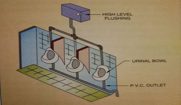
BOWL URINAL
Individual bowls are mounted on the wall as shown in the figure.
Bowls are fixed individually with/without division pieces between.
Material = Vitreous China
Size = Flat back 430 x 260 x 350mm (minimum)
Angle back 340 x 410 x 265mm (minimum)
Urinals are flushed by automatic flushing cisterns fixed above the urinal and discharging through a flush pipe.
The automatic flushing cistern is of 4.5 liter capacity per urinal and the cisterns can be adjusted to flush after. every twenty minutes.
One urinal requires the following fittings and materials
- Urinal = 1 No.
- Outlet horn coupling = 1 No.
- P.V.C. outlet pipe 32mm = 1 No.
- Flushing system 1 No.
- Generally, bathtubs are made of vitreous earthenware or fiberglass. They are also available in P.V.C. or fiber reinforced plastic (F.R.P.) material with various designs and colors.
- It is provided with hot and cold water connections and an inlet of 15mm dia each and an outlet of 32mm dia, connected to a waste pipe.
- The waste pipe is connected to the main vertical stack through a trap, so as to prevent the entry of foul gases in the bathtub.
- It is also provided with an overflow pipe to drain any excess water.
- Usual dimensions of the bathtub are 1.80m 1ength x 0.75m width x 0.45m depth.
- Overall height with its feet is 0.60m.
(h) BIDET
- Bidet is a sanitary fitting for washing the excretory organs.
- It consists of a bowl or pan shaped with an integral pedestal base. Bidets are made of vitreous china.
- Bidets are fit with an outlet of hot and cold water supply and spray (jet).
- A 75mm seal trap is fit to the outlet and connected to the 32mm waste.
- Cut the P.V.C. pipe with a fine-toothed saw to the required length.
- Chamfer the edge of the pipe to be inserted at an angle of about 15° to 1/3rd the wall thickness, using a coarse file.
- Make sure that the spigot and socket are thoroughly cleaned and are completely dry.
 |
| procedure jointing pvc pipes |
- Insert the pipe into the socket without the seal ring and mark along the pipe, after it is fully inserted.
- Fix the rubber ring into the groove, without twisting it.
- Apply to join lubricant to the chamfered end of the pipe, right up to the marking made on a spigot or to the socket end of the fitting.
- Push the pipe firmly into the socket until the gap between the mark on the spigot and socket is about 10mm to allow for thermal expansion if any.
(b) JOINING OF P.V.C. TO C.I.
- For joining P.V.C. to other materials, ensure that a rough surface (solvent cement base) is to be made on the P.V.C. pipe surface, before filling the gap with O.P.C. (ordinary portland cement).
- Ensure the following for joining cast iron long arm nahani trap into P.V.C. plug tee.
- Roughen the inside surface of the P.V.C. plug tee socket portion with a coarse emery paper.
- Apply a thin coat of solvent cement inside the P.V.C. plug tee socket portion with a small brush.
- Sprinkle some dry, medium-sized sand immediately over the solvent cement coat and let it dry for 5 minutes.
- This will give us a rough solvent base inside the plug tee socket for good bonding between the P.V.C. plug Tee and the C.I. nahani trap.
- Complete the joint by filling the gap between C.I. nahani trap and P.V.C. plug tee with cement.
- Important notes about solvent
- Solvent cement is a petroleum-based product (flammable). Keep it away from fire and direct sunlight.
- Solvent cement evaporates very fast if kept no open to sunlight and air. So, replace the lid of the solvent cement bottle immediately after use.
(c) JOINING OF CERAMIC TRAP TO P.V.C. CONNECTOR
- For joining E.W.C. P-trap, use P.V.C., W.C. connector with lipring which is specially designed to make a joint perfect between ceramic and P.V.C.
- Place the rubber lipring over the socket portion of the E.W.C.
- Apply rubber lubricant to the inside portion of the lipping and outlet of the E.W.C. P-trap.
- Then, fix the W.C. connector over the outlet of the E.W.C. P-trap. The joint is complete.
- Adopt the above-mentioned method for joining Indian W.C. pan P-trap to P.V.C. straight W.C. connector.
- For joining P.V.C. to P.V.C. (without rubber ring plain socketed ends), use solvent cement.
- Wherever P.V.C. pipes and fittings are passing through R.C.C. or
- should be made for P.V.C. pipes, for good bonding between P.V.C. and R.C.C. brickwork.
- Joining of P.V.C. horizontal and vertical lines should be carried ou simultaneously, ie. horizontal lines from the nahani trap to the external wall face and vertical lines between floor to floor.
- The adjustment is not possible in P.V.C. if the work of laying for horizontal and vertical lines is carried out separately.
5. INCORRECT USAGE BY THE OCCUPANT
- People tend to remove the cover mesh of the nahani trap and dump garbage in the trap. Though part of this is flushed away, greasy fibrous material sticks to the rough surface, leading to choke-up of the traps.
- They also try to remove the blockage by rodding, which leads to the breaking of the P-trap nahani trap. Choke remover is recommended in such cases.
- If eye covers (plug) are removed and not refitted properly, it leads to leakages.
- Ensure that the joint between fittings and pipe is complete.
- A rich mortar should be applied on the periphery of the hole and around the pipe.
- A suitable size of brickbats should be plugged in the mortar.
- Again a rich mortar should be applied on the brickbats, ensuring that the surface matches the external wall finish.
- Water-proofing compounds should be used in a mortar to ensure impermeability against leakages. Curing in the usual manner should be continued for at least 7 days.
EXTERNAL DRAINAGE SYSTEM
The network of pipes laid for carrying waste and night soil from the vertical stacks to the septic tank or sewer main.
A network of pipes usually comprises of 10cm dia. pipes for a branch line from the gully trap to the first chamber and 15cm dia. pipes for the mainline. Subsequently, the diameter of the sewer increases from manhole to manhole, as per the increase in discharge.
Usually, the following types of sewer pipes are used. They are available in various sizes.
- Stoneware glazed pipes
- Precast R.C.C. pipes
- C.I. pipes
2. FIXTURES AND FITTINGS
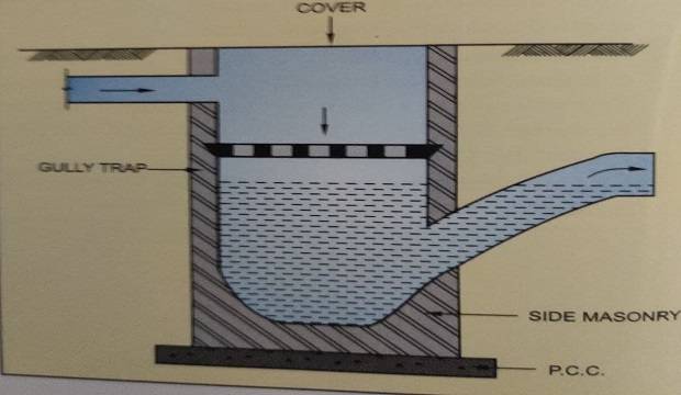
- Gully trap is made of stoneware clay. Normally 15cm x 15cm size is used.
- The water seal depth is 75mm.
- Used between sanitary fittings and the building drain.
- Used for admitting surface water from the yard and paved walks into the drain.
- A gully trap will disconnect a building from a building drain, by means of a 75mm water seal depth and thus prevent sewage gases from entering the building.
- The top of the gully trap must be deep enough to prevent splashing over.
- If planned carefully, sink and bath wastes can be discharged into one gully trap.
- Gully trap is so fixed that its chamber top is above the ground level.
- The chamber should be constructed on the gully trap. The size of the chamber should be 30cm x 30cm x 30cm.
(b) INTERCEPTOR (SEWER TRAP)
- Stoneware intercepting sewer trap is used before a building drain is connected to the public sewer.
- This trap has a water seal of about 10cm, which prevents the entry of objectionable, poisonous and harmful gases from public sewers into the building.
- Intercepting sewer is provided at the extreme end of the building drain adjoining the boundary of the premises near the public sewer.

3. PROCEDURE FOR LAYING SEWER PIPES
- Sewer pipes are laid beginning with their outfall ends towards their starting ends. The advantage gained in starting from the tail end (outfall) is the utilization of the tail sewers even during the initial period of construction.
- This ensures that the functioning of the sewage scheme does not have to wait until the completion of the entire scheme.
- Mark proposed alignment on the ground by locating the different points along the alignment.
- Locate the position where manholes/chambers are required, as per the drawing.
- Slopes in excavation should be provided using the side rail and rod method.
- Excavate trenches along the proposed alignment. The width of the trench at the bottom should be kept 15cm more than the outer diameter of the sewer pipe.
- Lay sewer pipes between the two chambers or inspection chambers.
- Keep the road passment position for the minimum crossing length of the sewer line.
- R.C.C. Hume pipes are generally used for such crossings. 10cm bedding concrete of grade M10 should be laid along the sewer line, up to half the depth of pipe which is called ‘haunching’, so that the sewer alignment is not disturbed. 10cm bed Concrete may be laid before the laying of sewer pipes.
- Manhole/chamber should be constructed at different locations, as per the drawings.
- Backfilling of trenches should be done immediately to avoid any accidents.
4. CONSTRUCTION AND FINISHING OF CHAMBERS (Inspection chambers)
GENERAL SPECIFICATIONS DETAILS
- Size 45cm x 60cm (18″x 24″) or 45cm x 90cm (18″. x 36″), depending upon the number of pipe connections entering the chamber, for two pipe connections use one chamber of 45cm x 60cm and for more pipes, provide 45cm x 90cm size inspection chamber.
- Location as per the drawing on the proposed alignment.
- Wall thickness 23cm (9″) of burnt bricks. Inside plaster smooth finished with extra cement in C.M. 1:4.
- External plaster – sand-faced plaster in C.M. 1:4.
- Gully Channel P.C.C. of grade M10, finished smooth with cement.
- Frame and cover – frame to be fixed in 10cm (4″) thick P.C.C. of grade M10, before internal and external plaster.
- Precast concrete covers for the chamber in the parking should be designed for vehicular loading.
- Bottom level 15mm (1/2″) below the incoming flow and flushed to the outgoing flow.
- Top of chamber same as the parking floor level road level.
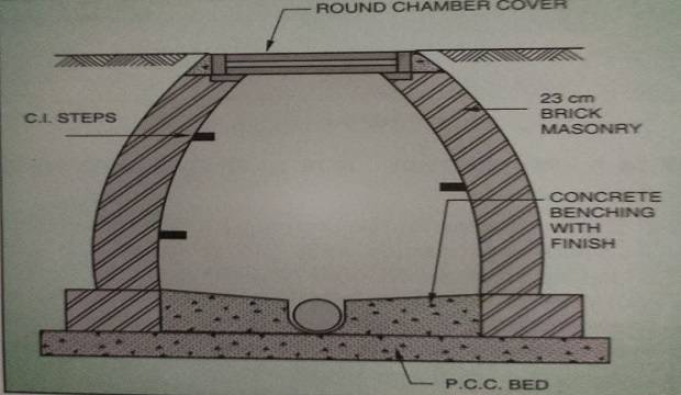
5. CONSTRUCTION AND FINISHING OF MANHOLES (ROUND CHAMBERS)
- Top diameter minimum 60cm (24″) clear.
- Bottom diameter As per the depth of the sewer line from ground level.
- Minimum 1.20m (for 1.5m (5′) depth).
- Location – AS per the drawing on the proposed main sewer alignment.
- Construction of the wall :
- Up to 1.8m depth-> 38cm to 23cm.
- More than 1.8m depth -> minimum thickness 45cm.
- Provide C.I. steps at the required height as per the drawings.
- Gully/channel – concrete of grade M10 should be laid in slope as 1:4, and finish smooth with e extra cement.
- Frame and cover – precast heavy-duty frame and cover.
- Frame to be fixed in 15cm (6″) thick concrete of grade M10, before internal and external plaster.
- Plaster Internal plaster in C.M. 1:4 finished smooth, with extra cement.
- External plaster in C.M. 1:4 rough finished for bottom half depth and trowel finished for the remaining depth.
- The bottom level sloped as per the sewer line.
- 15mm ( 1/2″) below the incoming sewer flow.
- Flushed with outgoing sewer flow.
- Top-level same as the road level on roads.
CHECKING AND TESTING OF DRAINAGE AND PIPES
- It is suitable for new drainage systems.
- It can be carried out between two consecutive manholes chambers.
- The lower end of the drain should be plugged with an expanding rubber stopper or with a flexible pneumatic stopper.
- The section of the drain under test is filled with water using a funnel, with approximately 60cm head above the highest joint.
- The highest joint should also be plugged and the funnel passed through it.
- Fill the water in the drain and leave for approximately 2 hours.
- Check the level in the funnel. A subsiding water level in the funnel indicates leakage in the drain section.
- Leaky joints or spots can be marked by more observation.
(b) AIR TEST
- Here, the pipeline section under test is plugged on both ends, and traps are fully water-sealed.
- Air is forced into the pipeline.
- Air pressure is adjusted to maintain the water seals in the traps (i.e. 7.5cm).
- Failure of the air to maintain water levels indicates leakage.
- Suspected joints may then be coated with a soap solution. This helps detect the spot/leaky joint from where the air escapes.
(c) SMOKE TEST
- It is suitable for waste systems, ventilating and soil pipes, and shallow drains in porous soil.
- All traps and lower ends are fully sealed.
- Smoke is introduced in the drain with a special machine or smoke rockets.
- Any leakage of smoke indicates the exact location of leaky joints.
2. TESTING OF LINEARITY, VERTICALITY, AND SLOPES
- Every drain pipe should have a proper slope to drain off the night soil or wastewater by gravity.
- Vertical stacks should be truly vertical. They enhance the appearance of the building.
- Horizontal sewer lines must be truly in line and at the required gradient, to maintain the smooth flow and to avoid the stagnation of flowing material.
- All vertical stacks should be properly clamped. A sufficient number of clamps should be provided on each floor. height, to maintain the verticality of the vertical stacks.
- All pipe joints and the respective fittings should be properly filled, to avoid leakage problems and the resultant maintenance.
- Trap joints that are embedded in water-proofing should be done with lead joints.
- The rest of the joints may be done with cement joints.
- Use solvent solution joints for P.V.C. pipes.
CAUSES OF LEAKAGES
Faulty plumbing is the result of
- The improper layout of the drainage pipelines or the choice of systems to be used is not correctly understood.
- Improper execution is also one of the major causes of leakages.
- Projections (burr) in traps or C.I. pipes where pieces of lints, pieces of cotton, match sticks, etc. remain, may lead to choke-up of the pipeline.
- Besides, tiny cracks, holes in pipes, traps, and other fittings also cause leakages.
- The connecting branch pipe should have a sufficient slope for self-cleansing velocity.
- The slope may not be maintained due to the long length and restricted depth of the sunken portion. The branch pipe should have a minímum length.
- The method of joining is also held responsible for leakages.
- Many joints are linked to the network of pipelines. If these joints are not properly filled, leakages can occur.
- To avoid leakages in floors where pipes are embedded, use lead joints, if possible.
- The inner circumstantial face of nahani trap, if not finished properly, allows wastewater to percolate.
GENERAL PRECAUTIONS FOR DRAINAGE WORKS
- The branch pipeline should be provided with a proper slope, minimum bends, and outlets with minimum joints.
- Bends should have a large radius.
- Fittings like a tee, bend, Y’ etc. should be provided with a clean-out or trap window at the proper locations in the pipe network.
- Embedding pipes below the masonry or floor should be avoided. At least it should be kept to the minimum required length.
IF YOU LIKE THIS POST PLUMBING AND SANITATION WORK PROCEDURE – ITEMS, USED IN BUILDING CONSTRUCTION LIKE THIS GETTING GOOD INFORMATION SO PLEASE SHARE THIS POST-SOCIAL NETWORK EXAMPLE FACEBOOK, TWITTER SOCIAL MEDIA SITES SHARE IT.
I really liked given above information.
Amaizing not with brief description thank you
amazing note tanx for the brief description please send full document by email.
Really a good effort in getting all info in presentation.
Congratulations
It is good material thanks so much
Too good
Very much detailed notes