Durable and has insulation and thermal property as well as the ability to be molded into the desired shape. Cement, sand, coarse aggregate, and water are the raw materials required for manufacturing reinforced cement concrete.
Rcc meaning: Reinforced Cement Concrete.
They are easily available. For tensile strength, steel is used in cement concrete. It is then termed the reinforced Cement Concrete (R.C.C.).
This material is not likely to be replaced easily by alternate building material.
Quality control in concrete construction checks the problems of the variability of ingredients and ensures proper workmanship for batching, mixing placing. compaction and curing of the concrete.
The main objective of quality control is to guarantee high quality, in accordance with the assumptions made in the design.
In this chapter, we will look at the quality aspects of building construction, workmanship, and the checks required for maintaining the quality of workmanship.
Tools required for concreting are almost the same as masonry work.

COMPONENT (RAW) MATERIAL REINFORCED CEMENT CONCRETE AND ACCEPTANCE CRITERIA
Ordinary portland cement is the most widely used cement for making reinforced cement concrete. 43 Grade & 53 Grade of cement can also be used. On the arrival of cement on the site, the following field tests should be carried out before using it.
Reinforced Cement Concrete Notes Pdf Download Link Below

Field tests for cement.
- Check the weight of the cement bag with a weight balance. The weight of the bag should not vary more than 2% of the standard weight of the cement bag i.e. 50kg.
- Ensure that the original packing of the company is intact. Ensure that the company’s brand & grade is as per the order placed.
- Check the manufacturing date of the cement which is written on the bag, to know how old the cement is. Always use fresh cement for quality reinforced cement concrete.
- Ensure that there are no lumps by feeling the cement in the bag manually.
- The cement should feel cool to the hand immersed in the bag.
- The cement should feel silky smooth when rubbed.
- Add a handful of cement slowly to a bucket full of water. The cement particles should float for some time before sinking.
- Prepare 5cm x 5cm x 5cm cubes from the cement paste. Keep them immediately in water. After 24 hours, the edges of the cubes should
- remain sharp and should gain in strength.
 |
| Information about cement bag |
2. COARSE AGGREGATES
Aggregates which pass through the I.S. sieve of the opening of size 80mm and are entirely retained on 4.75 mm I.S. sieve, are known as coarse aggregates.
The sizes of the particles to be used for reinforced cement concrete depend on the type of work and reinforcement. Coarse aggregates consist of aggregates such as stone gravel.
- Should not be porous, as porous material corrodes the reinforcement.
- Elongated and laminated particles are good in shear.
- Must be clean and free from clay lumps, vegetables, and other organic material. Clay dirt in the aggregate slows down the setting and hardening of cement and reduces the strength.
- Angular and roughly cubical particles are ideal.
- 25mm & 12.5mm size coarse aggregates are normally used in R.C.C. works.
- For mass concrete, up to 40mm size coarse aggregates can be used.
- The maximum size of coarse aggregates should be within the limits specified.
What is RCC | Concept of Reinforced Cement Concrete | Introduction to Reinforced Cement Concrete
3. FINE AGGREGATES
Sand is used as fine aggregate to fill voids between coarse aggregates, for producing dense reinforced cement concrete. Sand passes through a 4.75mm I.S. sieve.
Sand should consist of sharp angular grains of various sizes. Recent studies show that rounded grains too interlock sufficiently, to produce strong concrete.
ACCEPTANCE CRITERIA
- Ensure that the sand is river wet or artificially wet (to increase the bulkage).
- Check if the fineness (type) of the sand supplied is as per the purchase order.
- Sand should be free from silt, clay, salts, mica, and organic material. Sand is generally found to. contain some percentage of silt and clay. Maximum 7% of silt and clay may be allowed in the sand at construction sites.
BULKING OF SAND
When the moist sand is measured by volume, allowances should be made for bulking.
|
|

The percentage of bulking of sand due to moisture content, can be calculated by a simple field method.
- Take the sample of moist sand in a glass cylinder of 250Oml capacity.
- Shake the cylinder and note down the consolidated sand reading as A.
- Pour water in the cylinder, above the sand level, and shake well.
- Allow the contents to settle. Take the reading for submerged sand as B.
- Then a percentage of bulking of sand due to moisture can be calculated by using the formula – A – B / B X 100.
TEST PRESENCE SILT OR CLAY IN SAND BY VOLUME
- Rub a sample of the sand with wet palms. Good, the clean sand will not stick to the hand, whereas sand with silt clay will stick, changing the color of the palm.
- Fill half a glass cylinder with sand and pour clean water until the cylinder is full.
- Shake it vigorously and leave it to settle for about an hour.
- Clean sand will settle immediately. Any clay will make the water muddy. Clay or silt will also settle gradually above the sand.
- Add a teaspoon of salt to the water. It will quicken the process and a layer of silt will settle above the sand.
- The thickness of the silt layer should not exceed the thickness of the sand layer, by 7%.
- If the percentage of silt is more, the sand needs washing.
DISADVANTAGES OF MORE SILT CONTENT
Clay forms a film on the particles of sand and prevents reduces the adhering of cement to the sand particles, retards the setting of cement, increases drying shrinkage, and increases the amount of water required for the mix; ultimately reducing the strength of the reinforced cement concrete mortar.
4. REINFORCEMENT (STEEL)
H.Y.S.D. (High Yield Strength Deformed) steel bars are generally used as reinforcement in concrete. The field tests for reinforcement are discussed in this chapter at a later stage.
5. WATER
5. ADMIXTURES
Admixtures are ingredients other than cement, water, and aggregates that are added to the mixture immediately, before or during the mixing of concrete.
- Air entraining admixtures
- Water reducing admixtures
- Retarding admixtures
- Accelerating admixtures
- Superplasticizers
- Miscellaneous admixtures are useful for workability, bonding, damp proofing. gravity etc.
The major reasons for using admixtures are
- To achieve the economy in concrete constructions.
- To achieve certain properties in reinforced cement concrete more effectively than by any other means.
COMPACTION OF CONCRETE
-
Rodding
-
Ramming
-
Tamping
- Internal vibrator (needle vibrator)
- Form-work vibrator (external vibrator)
- Table vibrator
- Platform vibrator
- Surface vibrator (screed vibrator)
A. RODDING
B. RAMMING
(a) INTERNAL VIBRATOR
The common needle diameters are 25mm & 40mm and the length varies from 25cm to 90cm.
 |
| needle vibrator |
(b) EXTERNAL VIBRATOR
It is also called the form-work vibrator. For columns, thin walls, and thin pre-cast units, form-work vibrators are used. The machine is clamped to the external wall surface of the form-work and shuttering is then vibrated. The efficiency of this type of vibrator is less than the efficiency of an internal vibrator.
(c) SURFACE VIBRATOR
3. PRECAUTIONS AND CHECKS OF VIBRATOR AND IT’S USE
- Proper vibrations to the needle.
- The diameter of the needle to be checked for the required size.
- Normally used diameters are 25mm and 40mm.
- One spare standby needle should be there.
- Check the quantity of fuel.
- Check the starting and continuous running of the vibrator for at least fifteen minutes.
- The spark plug is to be cleaned periodically.
- Avoid over-vibrațing.
- Check the shuttering during vibrating for damages (bulging).
- Switch off the flows out from the shuttering.
- Do not stop the vibrator when the needle is in vibrator if cement slurry
- the concrete.
CURING OF CONCRETE
1. IMPORTANCE OF CURING
2. METHODS OF CURING
- Water curing
- Membrane curing
- Application of heat
- Miscellaneous
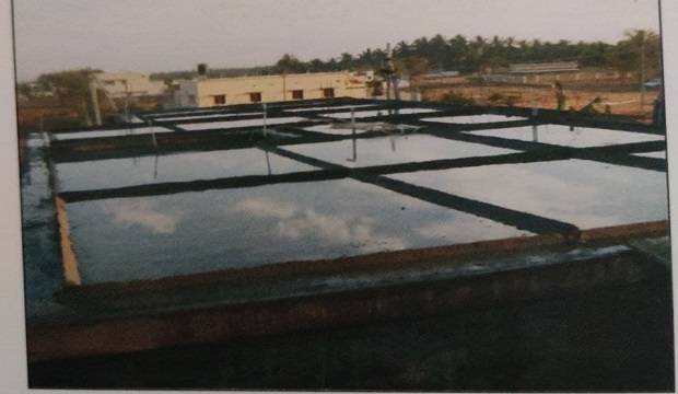
A. WATER CURING
PONDING – Floor slabs, road covered by water by making small ponds of water.
SPRAYING AND WET COVERING
Retaining walls and concrete columns are cured by spraying water. In some cases, wet coverings such as wet gunny bags, Hessian cloth, etc. are wrapped around the vertical surfaces for keeping the reinforced cement concrete wet.
B. MEMBRANE CURING
During an acute shortage of water, it is not possible to cure the concrete with an ample quantity of water. In such cases, membrane curing is done.
The basic concept behind membrane curing is that the water used to mix the concrete is not allowed to go out from the body of concrete. Obviously, this water helps in uninterrupted and progressive hydration.
C. APPLICATION OF HEAT
When concrete is subjected to higher temperatures along with moisture, it accelerates the hydration process, resulting in the development of strength.
For this, the following processes are found useful.
- Steam curing at ordinary and high pressures
- Curing by Infra-red radiation
- Electrical curing
Applying calcium chloride on the surface of the concrete member is useful for effective curing.
Calcium chloride is salt and shows an affinity for atmospheric moisture-retaining it at the surface.
In the case of beams and columns, form-work prevents moisture from escaping the concrete; thus promoting hydration of concrete.
What are Different Tests for Concrete Quality Check?
(a) SLUMP TEST
- Bottom diameter 200mm.
- 100mm.
- 300mm.
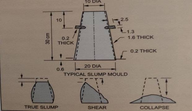
PROCEDURE OF MEASURING SLUMP
- The rod should penetrate every underlying layer.
- Strike off excess concrete clean the internal surface of the mould.
- Fill the mould with concrete in 4 layers.
- Tamp each layer with 25 strokes of the rod.
- Distribute the strokes uniformly over the entire cross-section of the mould. after the top layer, with a trowel.
- Remove the mould slowly and vertically.
- The concrete will slump or slide.
- Measure the height of the slump in mm.
- For normal workability, the slump should not exceed 50mm.
- Clean the slump cone.
(b) TEMPERATURE OF FRESH CONCRETE
This test is carried out to determine if fresh concrete is too hot or too cold. Hot concrete stiffens rapidly and develops lower strengths at later stages. As per the I.S., in hot weather, thetemperature of hot concrete should not exceed 38 degrees centigrade while placing. In cold weather, a minimum temperature of 4.5 degrees centigrade is prescribed for the concrete at the time of placing.
Minimum 3 liters of fresh concrete is required for the test. At least 3 readings in different parts of the batch should be taken. If the concrete is too hot. the subsequent batches can be mixed by using cold water. Also, cool the aggregates by sprinkling them with water.
2. LABORATORY TESTS OF HARDENED CONCRETE
Making cubes & curing for the required period.
- To check that the mix proportions are adequate for the strength prescribed as a basis for acceptance for quality control.
- To determine the time of removal of forms when a structure may be put into service.
- To assess the 28 days compressive strength of the concrete in 24 hours, using accelerated curing methods such as the boiling or warm water method.
B. PROCEDURE FOR CASTING OF CUBES
- Clean the standard cube moulds, 6 Nos. thoroughly & tighten all the nut-bolts properly.
- Apply oil to all contact surfaces of the mould. The size of the mould is normally 150mm x 150mm x 150mm.
- Take random samples from the mix in a ghamela, while concreting.
- Pour concrete into the cubes in 3 layers.
- Compact each layer with 35 Nos. of strokes with the tamping rod.
- Finish the top surface by thapi trowel after compaction of the last layer.
- Cover the mould by a damp Hessian cloth immediately to prevent loss of water.
- Each specimen should be taken from different locations of the proposed concreting.
- After 24 hours, remove the specimen from the control of the quantity of three the mould.
- While removing, take care to avoid breaking of the edges.
- Code the cubes with paint or marker. Coding should be self-explanatory, showing the site name, concrete location, building no., and the date of casting.
- Submerge the specimen in clean, fresh water until the time of testing.
- Test 3 specimens for 7 days & 3 specimens for 28 days curing concrete.
C. TESTING OF CONCRETE CUBES
- Check the coding & numbers of cubes received.
- Enter the details of the cubes in the testing register.
- Weigh the cubes & note the figures in the register.
- Inform the concerned person about any damages.
- Check the dates of casting & testing for 7 & 28 days.
- Place the cubes in the testing machine, so that the load is applied to the opposite side of the cube as case i:e, not on top & bottom. (Opposite sides of the cube surfaces are in contact with sides of the metal mould).
- Apply the load without interruptions & increase the load continuously, at a rate of approximately 400kg/min until the resistance of the specimen breaks down & no additional load can be sustained.
- Record the maximum load applied to the specimen.
- Observe the appearance of concrete connection with the failure & note the same.
- Calculate
- compressive strength = (Maximum load at failure.) / (Contact Area of the cube.)
- Take average strength of 3 specimen cubes.
- This average strength represents the strength of concrete of a particular portion of the structure.
- Prepare the test report & submit to higher authorities.
- Cubes of the same lot should not vary.
- Inspect the particular portion of the structure immediately, if results are considerably below normal.
D. AGE ATTEST
Tests shall be carried out at ages prescribed for the test, the most usual being 7 days and 28 days.
E. PRECAUTIONS
- Remove the mould after 24 hours and store the specimens in clean, fresh water.
- The place where specimens are stored shall be free of vibrations.
- The water in which the specimens are submerged shall be replaced every 7 days.
- Specimens shall not be allowed to dry out at any time before testing.
3. NON DESTRUCTIVE TESTS ON HARDENED CONCRETE
Following are a few non-destructive tests generally performed
- The ultrasonic pulse velocity test
- Rebound hammer test
- Test on cores cut from hardened concrete.
The purpose of carrying out these tests are
- To determine the uniformity of concrete in/between members.
- To detect the presence and approximate extent of cracks, voids, and other defects.
CHECKLIST FOR CONCRETING WORK
1. COLUMN CONCRETING ABOVE PLINTH FLOOR SLAB
- Plotting of grid lines for the center of the column above the plinth floor slab.
- Locating and marking the centers of columns.
- Binding & placing column reinforcement above the upper floor slab, as per the required height, considering lap length of the bar.
- Check for column reinforcement & their arrangements as per the drawing.
- Ring spacing and their arrangements as per the R.C.C. drawing.
- Proper binding of reinforcement with binding wire.
- Fixing concrete or P.V.C. cover blocks to reinforcement.
CHECKING OF SHUTTERING FOR COLUMNS
- Check the quality of shuttering before placing it.
- Applying de-shuttering oil to plywood shuttering.
- Fixing of shikanjas (M.S. clamps) at every 60cm (2′.00″) interval.
- Checking the stiffness of side supports, applied to the form-work in plumb.

CHECKING OF COLUMNS BEFORE CONCRETING
- Size as per drawing
- To check diagonals.
- Oiling of shuttering
- Plumb on both sides
- Line
- Level marking up to which concrete is to be done
- Supports.
- Reinforcement cover on top
- The spacing of reinforcement above the concrete level.
- Sufficient lap length.
- Proper filling of gaps from outside with soil paste
CHECKING OF COLUMN WHILE CONCRETING
- Check the quality of the material.
- To check the proportion and mixing of material.
- To ensure that six cube moulds are kept ready to cast cubes from different batches.
- Controlled water-cement ratio.
- Availability of vibrator or labour for tamping.
- To ensure proper cover after concreting on the top level.
- Casting of concrete cubes as required.
- To ensure proper numbering on cubes.
- Check all joints to ensure that no slurry flows from anywhere.
- To check for the required concrete level.
- Check the cleaning of the mixing platform.
CHECKING OF COLUMNS AFTER CONCRETING
- De-shuttering of columns after 36 hours.
- To submit the de-shuttering report to higher authorities.
- Finishing the honeycombing carefully.
- Date of casting and column number to be written on the column.
- Hacking (Tacha) of columns 50 numbers in 1s.ft. (500 Nos. in 1sq.m.).
- Cubes to be removed the next day and kept for curing, with a code number, casting date, and site name.
- Curing of columns to be done for a minimum of 15 days, with wet Hessian cloth rapped around them.
- Testing of cubes on due dates, i.e., after the 7th and 28th days.

2. SLAB BEAM CONCRETING
Points to be noted for checking of slabs before casting,
CHECKING OF SHUTTERING
- Height of slab from the plinth slab level.
- Quality of shuttering material.
- To ensure fixing of the cap on the column to take the load.
- Width of the beam bottom plank. To ensure proper fixing of the beam bottom over the cap.
- Line and level of the beam bottom.
- Depth of beam as per the R.C.C. drawing.
- Proper fixing of props for the bottom in line and plumb, at every 2’0″ (0.60m) interval.
- For packing the below props, only one or two wooden plank pieces are allowed. (Brick or blocks are not permitted).
- Bamboo bracing for joining, prop to prop, at 4’0″ (1.2m) height from the floor.
- Proper fixing of the side of the beam in line, level, and plumb.
- Support to the vertical joint of shuttering for 24″ (0.60m) beam or 3O” (0.75m) beam.
- Gaps in beam sides should be filled.
- Ensure fixing of the steel plates over beam sides, in flush position.
- Slab plates should be supported by 3″ x 3″ (75mm x 75mm) chawis at 2’0″ (0.60m) distance, centre to centre.
- “Side plank’ for slab panel periphery.
- Individual-level of each bay of the slab.
- Mark the thickness of the slab.
- Check if the joints of the plate and ghabadi work is watertight.
- Oil the slab plates.
- Internal panel measurements, beam to beam & diagonal of the panel.
- Location and depth of the sunken slab.
- The outer line of beam sides.
- Check for room sizes & diagonals.
- Check if the junctions of columns and beams are watertight.
CHECKING OF REINFORCEMENT FOR BEAMS
- Bottom bars, top bars, bent-up bars, stirrups, a distance of bent supports, extra bars over the supports, the spacing of the stirrups as per the R.C.C. drawing, proper tying of the stirrups.
- The diameter of bars, binding of stirrups in plumb.
- Length of bent-up bars continuing in adjacent beams.
- ‘L’ for bent-up bars at discontinuous ends.
- Side covers and bottom covers for beams.
- Check if a pin is provided at required places, i.e. more than 3 bars in one layer, for 15cm (6″) wide beam. Also, check the spacing and diameter of the pin provided.
- Proper binding of laps in beams, if provided with the required length.
- Extra stirrups at the junction of the beam.

- Spacing, a diameter of bent-up bars, and main bars.
- The distance of bent-up bars from the face of the beam.
- Length of bent-up bars projecting in the adjacent panel.
- Height of the bent-up bars.
- The chair below every bent-up bars.
- Covering for the slab at the bottom.
- Proper binding of laps of the required length.
- Distribution steel diameters, spacing, and ties.
- Check dowels of slab & beam.
- Location, proper binding diameter & length of fan hook, and quality of the fan hook box.
- Put stirrups in the column for upper floor column size.
To check the concealed electric conduit work for the slab, as per the drawing and I.S.I. mark on the P.V.C. pipes. Note down the length of all pipes for billing purposes.
- Check the junctions and all electrical points as per the electric layout, the position of fan points, M.S. boxes, junction boxes.
- Avoid breaking of pipes during concreting.
- Check the slab & the certificate from the architect.
- Check the slab & obtain a certificate from the R.C.C. consultant.
- Sieve analysis for sand to be carried out in advance, for the concrete mix design.
- To measure the silt content ofsand.
CHECKLIST AFTER CONCRETING
- De-shuttering of outer beams after 24 hours.
- Make small ponds in sand and cement mortar (1:10) for the pounding method of curing for the slab with a minimum size of 2.0 m x 2.0 m (6’0″ x 6’0″).
- Check any waste of material like sand, metal, and steel cut-pieces.
- De-shuttering of internal beam sides after 48 hours.
- Curing of a slab for 28 days.
- Paint work the date of the casting of a slab, on the front beam.
- Register the slab in the head office, the day
- after casting.
- De-shuttering of the slab after 7 days, 10 days, or 15 days, depending on the span.
- Hacking of beam sides, bottom, slab bottom.
- Checking all honeycombing surfaces & if finishing is to be done with rich mortar.
- For more honeycombing, consult the R.C.C. consultant.

FORM WORK
1. DEFINITION
2. REQUIREMENTS OF A GOOD FORM-WORK
- The form-work must be water-proofed, so as to prevent the absorption of water from the concrete.
- The form-work must be strong enough to bear a load of concrete, workmen, the liquid pressure of the fresh concrete, and the impact effect of ramming or vibrating.
- The form-work should be as light as possible and stiff enough to have the minimum deflection.
- All joints in the form-work should be true and the surface should be plane to minimize the cost of surface finishing.
- The form-work should be easily removable without damages.
In this type of form-work, the material could be steel plate, plywood wooden plank or wooden prop.
Steel Plate Size
Size of steel plates are different : i.e., 3’0″ x 2’0″ x 1″ (90 cm x 60 cm x 25 mm) thick plate is generally being used but plates in size 4’0″ x 2’0″ (120 cm x 60 cm), l’6″ x 3’0″ (45 cm x 90 cm), 0’9″ x 3’0″ (23 cm x 90 cm) etc. are also available.
Plywood should be stiff, water-proof, and a higher usable value.
Size of plywood 4’0′ x 8’0′ (1.20m x 2.40m) or 3’0′ x 8’0 (0.90m x 2.40m), thickness of plywood should be 10 to 12mm for the above work upto a depth of 2’0″ (60cm) concrete.
WOODEN PLANKS AND PROPS
Planks
Quality of wood to be used of the silver oak type and should be free from knots, twists, shakes decay, and imperfections which could otherwise affect the strength of forms and finished surface of the concrete.
Check the clear width of the planks used. Usually when we place an order for 6″ (15 cm) width planks, after cutting & finishing we receive 5″ (14.5cm) width planks, due to which the total measurements of beams & bays will be affected.
Prop
The diameter of props should not be less than 3″ (7.5cm) and it should be straight, as far as possible.
(b) STEEL FORM-WORK
Steel form-work is the more expensive type of formwork, as it is made completely of steel. This shuttering is easy to erect and to de-shutter. The manpower required is very less.
True horizontal and vertical planes of concrete surface can be got, with the help of steel form-work which ultimately reduces the thickness of the plaster and cost of construction. Nuts and bolts are used to clamp the sides of beams, to prevent bulging of the sides.
 |
| steel centering system and its components |
ADJUSTABLE PROP
The props used for steel form-work are specially made to adjust the height of the prop as per the requirement. These props can be used to accommodate the variations in the height of the beam, slab, and all R.C.C. members. It is especially useful for heavy load-bearing capacity, is very simple in operation time and labor-saving.
PROPEX
Propex is basically used where the height is greater than practical. More height for props in two or three tiers requires vertical adjustment to the exact height and can be obtained by inserting a “PROPEX” at the top of each scaffold.
ADJUSTABLE SPAN
Adjustable spans are used to support the centering plates for the shuttering of the slab. No prop is required in between, so plenty of space is available below the slab shuttering. This can be adjusted for any length between 2.0m to 4.0m.
Sizes available
1. 2.0-3.0m (Junior span)
2.4-4.0m (Senior span)
- These are the totally bolted type for easy assembly and removal after casting.
- Rolled sheets offer an excellent finish of columns after casting.
- Fabricated art of pressed sheets for lightweight
- Sizes adjustable from 225, 300, 375, 450mm.
- Fully bolted construction
- Available in 1200mm and 2500mm height
- Very easy to erect
- The guaranteed quality finish of the concrete surface
- No wastage, as in wooden form-work
- Required for clampingthe column and beam shuttering.
- It allows quick and rigid clamping of formwork.
- Ensures (squareness) or the required size of the column after correcting.
- Four arms types with edges at four corners can be used for columns.
- For beams, a single-legged type clamp can be used.
This type of centering can be used for staircases.
- Adjustable in length
- Flexible utility for almost all widths of a staircase
-
900 to 1400mm
-
1000 to 1500mm
All sizes mentioned in steel form may change as per manufacturers’ standards.
3. WORK PROCEDURE FOR FORM WORK
(a) FORMWORK PROCEDURE FOR FOOTING
- After completing the excavation for the column and footing, check the size of the pit before P.C.C.
- Allow P.C.C. work.
- Check the level of P.C.C. Then mark the center of the footing in a cement mortar on P.C.C., with the help of side rail or centerline pillar.
- Place the footing form-work box, check the size and diagonals of the form-work box.
- Check for gaps if any between form-work and P.C.C. top level.
- Before concreting, clean the inner space of the box and P.C.C. with the help of a water jet.
- Give proper supports to the footing box, so that its position should not change.
- Mark centers of the footing with the help of a nail, on footing box, or planks.
- The Centre marked on the footing box should match the center marked on the side rail or centerline pillar.
- Check the reinforcement of footing, column, and concreting depth of footing and allow for concreting.

(b) FORMWORK FOR COLUMN
QUALITY OF MATERIAL
- The material should be water-proof.
- There should not be any curvature in the plywood used for form-work.
- Supports to plywood should be sufficient in both vertical & horizontal directions.
- Proper care should be taken before placing column form-work.
- Check the dimensions and diagonals of the form-work box of the column.
- Fix M.S. clamps in sufficient quantity, to prevent bulging of the column during concreting.
- The rectangular and round column formwork sides should be as shown in the figure.
- After marking the centerline of the column, check the minimum coverage, and check the column reinforcement.
- Give appropriate cover using cover blocks for column reinforcement.
- Give supports for the column in the vertical.
- position. Supports should be tight. Provide the supports with bracing to adjacent side columns to avoid the rotary movement of the column.
- Check any gap at the bottom and fill them with carpenter’s putty or any filling material.
- Calculate & mark the permissible concreting level considering beam depth etc. with a nail.
- The de-shuttering period should not be less than 24 hours.
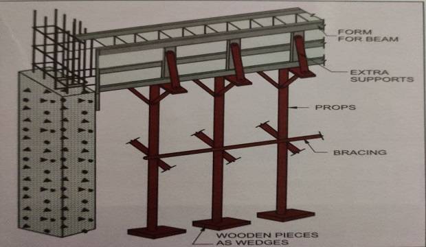
(c) FORM-WORK FOR BEAM
- Mark one level on every column.
- Check the position and level of the beam bottom supports (topi), with respect to the depth of the beam.
- The width of ‘topi’ should be the same as the width of the beam.
- Topi’ should be fixed firmly to the column with the help of binding wire and 2 “(6cm) nails in plumb.
- A top cut of ‘topi’ should not be in the cross.
- The bottom plank of the beam should not bend but be in a straight line.
- Check the level of the beam bottom before providing beam sides.
- Provide bracing to beam bottom supports after leveling the beam bottom. Supports should be perfectly vertical (props).
- There should not be any joints in props.
- Props should be as shown in the figure.
- Joints in beam sides should be as shown in the figure.
- Check the plumb of beam sides at each end & with the help of line Dori, fix the straight line of beam sides.
- Joints in beam sides should be taken at the end of the beam.
- Check the column & beam joint. Shuttering here should be plumb.
- Check the depth of the beam.
(d) Work Procedure Slab
- The plate should be of uniform thickness.
- The plate should be in the perfect right angle.
- Check the level of the slab with tube level or dumpy level.
- Form-work of the slab should be done after floor P.C.C. is completed and fully cured.
- Oil the centering plates before placing the reinforcement.
- Adjust the side edge plank (Dhar Patti), along with the beam sides as per the dimensions of each bay & the available size of the plate to avoid voids (ghabadi) in between.
- The spanning of the plate should be as shown in the figure. Supports to slab should be at 2’O” (0.60m), center to center.
- Put chavi of size 4″ x 4″ (0.10 x 0.10m) to support the slab plates at 2’0″ (0.60m) c/c. Chavi should be supported with a straight prop.
- Use adjustable plates (ghabadi plate) to adjust unavoidable ghabadi in a particular bay.
- Do not put bricks or blocks below the prop, to adjust the height using wooden wedges.
- Bracing should be provided for each prop to avoid lateral movement.
- All M.S. plates should be properly adjusted.
- No portion of the plate should enter the beamwidth.
- Check the line, plumb, and supports of beam sides.
- Fill the gaps between plates with papers or putti.
- Prop of slab centering plates should be perfectly vertical at required spacing, minimum 2’0″ (0.60m) c/c.
- Check whether the slab thickness is marked on the side of the slab or nails are driven in the plywood sides as per the thickness of the slab.
- Mark the thickness of slabs to be filled with concrete on every column bar, with binding wire for slab and staircase slab.
- Check the shuttering as per the checklist before placing reinforcement. For staircase form-work.
(e) FORM-WORK FOR CHAJJA
- Chajjais a part projecting outside the building, for protecting the window frame fixing from rains. It is generally designed as a cantilever.
- The following precautions should be taken while doing the shuttering of the chajjas.
- The lintel bottom is fixed using planks on the masonry walls.
- After checking the line and level of the lintel bottom, proper supports are given to it.
- As per the width of the chajija M.S. plates are fixed in the level of lintel bottom with slanting supports as shown in the figure.
- Cross-bracing is given to these slanting supports and the base of such supports are prevented from sliding with the help of wooden wedges fixed on the window sill masonry as shown in the figure.
- Reinforcement is tied as per the drawing.
- Sides of chajjas are fixed along with the sides of the lintel.
- The inner side of the lintel is kept hanging for homogeneous concreting of lintel and chajja. (this is called Tang side’)
- Proper tying for firmness is done with binding wire.
- The width of the lintel is maintained with wooden pieces of the required length trapped between the sides of the lintel.
- Concreting is done on the slope as per the drawings.
Shuttering of an overhead water tank should be done with scaffolding around the water tank as shown in the figure. Check the corners of the water tank. They should be perfectly at right angles.
Generally, steel plates are used for side shuttering of water tanks. They should be planes and at the right angle. Check the dimensions and diagonals of the All other precautions should be the same as the shuttering of the slab beam. water tank.
4. DE SHUTTERING OF FORMWORK
(a) PRECAUTIONS TO BE TAKEN DURING DESHUTTERING
- While de-shuttering the form-work of col ensure that the edges of columns are protected.
- While de-shuttering the external sides of the floor beams, ensure that nobody is working in the nearby area, so as to prevent possible
- accidents.
- While de-shuttering the internal beam sides, ensure that supports of slab and beam bottom are not disturbed.
- De-shuttering of slab plates should be done after making scaffolding. No plates should be removed from the slab without proper scaffolding. Also, ensure that nobody is working in the nearby area.
5. NEGLIGENCE OF CONTRACTORS WHILE DOING FORM-WORK
- For column form-work, contractors use binding wire in place of shikanjas.
- In column reinforcement, normally they avoid the stirrups or rings from beam bottom to the top of the slab.
- For support to beam bottom at the column, contractors use wastage material for topi (cap).
- Disadvantages of Topi made from waste materials are.
- Improper fixing of topi affects the plumb of the column.
- Cross-cutting of topi affects the level of beam bottom.
- Contractors are not interested in repairing the small’ ghabadi’, . This affects the strength of the reinforced cement concrete because all cement slurry flows away from these ghabadior gaps and after de-shuttering, honeycombs are observed in such parts.
- For slab form-work where it is not possible to
- place plates, contractors use scrap material. In such cases, after de-shuttering the concrete surface at the bottom of the slab is not found at the proper level. It affects the thickness of the plaster. So, insist that he must use new planks for all ghabadi work.
- While de-shuttering the slab, carpenters drop steel plates from the total height of the slab, i.e. from a minimum 2.75m (9′.00″) causing accidents. So, de-shuttering for the slab should be done with the help of scaffolding.
| SR NO. | ITEM | MINIMUM PERIOD FOR DESHUTTERING |
| 1 | COLUMN | 24 HRS |
| 2 | SIDE OF BEAM | 24 HRS |
| 3 | BEAM BOTTOM UPTO 3 M | 14 DAYS |
| 4 | BEAM BOTTOM ABOVE 3M | 21 DAYS |
| 5 | SLAB SPAN UPTO 3.5M | 07 DAYS |
| 6 | SLAB WITH SPAN BETWEEN 3.5 TO 6M | 14 DAYS |
| 7 | SLAB OF SPAN MORE THAN 6M | 21 DAYS |
- Normally, white oil or centering oil should be applied to the form-work in the required quantities. Extra oiling of the form-work affects the bonding of steel with concrete. The oily surface of reinforced cement concrete affects curing. So, curing for column, beam, the slab cannot be done properly.
- Contractors provide only a single type of bracing for props. It should be done in two directions, i.e., all props should be supported with bi-directional bracing at the same level.
- Contractors prefer early de-shuttering to speed up the work with minimum shuttering. Follow the de-shuttering period chart. Do not allow early de-shuttering.
- Contractors use less number of nails & insufficient supports to the joint, which may result in joints which are not tightened.
- To avoid cutting of props, contractors fix the prop in a slanted position or give more packing from the bottom to utilize short props.
- Contractors avoid making holes in the shuttering ply for straight horizontal projecting dowel bars. The bar should be bent vertically inside the shuttering only.

REINFORCEMENT IN CEMENT CONCRETE
There are two common types of reinforcing bars,
- Mild steel bars C.T.D. (Cold Twisted Deformed)
- High yield stress deformed bars (H.Y.S.D.)
| BAR TYPE | GRADE OF STEEL | YIELD STRESS N/MM2 | MIN % OF ELONGATION AT FAILURE |
| M.S ROUND | FE 250 | 250 | 23 |
| H.Y.S.D. (TOR 40) | FE 415 | 415 | 14.5 |
| H.Y.S.D. (TOR 50) | FE 500 | 500 | 12 |
Generally, mild steel of 6mm diameter is used as secondary reinforcement and C.T.D. steel bars of diameter 8. 10, 12, 16, 20, 25, 32 & 40mm are used as main reinforcement.
ADVANTAGES OF TOR STEEL
- Higher bond strength
- Better fatigue strength
- Less crack width due to high bond
- Satisfactory bendability
- 100% weldability
- Suitable for main & distribution steel
- Cost-effective
-

typical steelyard, steel stacking
- The pitch length between the twist should be 8 to 12 times that of the nominal diameter of the bar.
- The diameter of the bar should not vary. For measuring the diameter of bars, a Screw Gauge or Vernier Caliper should be kept on site.
- Steel should not be brittle in nature but soft for working. It should not break into pieces during bending.
- The length of the bar should be between 11 to 12 meters.
- Steel should not be corroded. This can be checked by the rusting layer on bars and by taking the weight of the steel bar before and after immersion in water for 24 hours. The loss of the weight of steel shows the depth of corrosion.
- In the case of TOR’ steel TOR,’ a mark should be present on each meter length.
- The binding wire should be of 16. gauge.
- It should be soft in working and should not be brittle.
- When tied, it should not loosen from its position.
- It should not be corroded.
The actual weight of steel can be calculated by subtracting the empty weight of the truck from the weight of the loaded truck, both weights to be taken from the same weight balance.
The approximate theoretical weight of the steel bar in kg meter should be calculated as (d2 ÷ 162), where ‘d’ is the diameter of the bar in mm.
3. STACKING OF THE STEEL
- Stack in the steelyard only.
- Bars should not touch the ground to avoid rusting of bars.
- Spread shingle in the steelyard to prevent direct contact of soil with steel bars to avoid rusting.
- Stack diameter-wise.
- Steel stack should be on reinforced cement concrete blocks at a height of at least 30cm (l’.0″) above ground level.
- Separate space should be kept for cut pieces.
- G.I. sheet steelyard should protect from subsoil water, all around by putting murum soil on all four sides.
- Separate space should be provided in the steelyard for ready beams, rings, etc.
- Proper access for truck movement should be provided from the main road to the steelyard.
BENEFITS OF A STEEL YARD
- It allows sufficient space to stack steel of different diameters separately.
- Sufficient space to R.C.C. fitters for working outside the steelyard.
- Controls the possible thefts of small steel pieces as the working of the fitter is inside the steelyard.
- Controls any wastage by the fitters.
- Full utilization of ‘rejas’ (small cut pieces) in beams, slabs, lintels, lofts, etc.
- Locking arrangements can be made for individual stacks to prevent theft and check that the fitters utilize available ‘rejas’ before taking new steel.
- Overall security can be maintained by locking the main gate.
4. BAR BENDING SCHEDULE
(a) NECESSITY OF BAR BENDING SCHEDULE
Bar bending schedules help the site engineer and R.C.C. fitters to give the exact cutting length of steel, required for each member, i.e., beam, slab, column, etc. This reduces the wastage of steel. With the help of a bar bending schedule, the site engineer can calculate the exact quantity of steel required for slabs and beams. A counter-check on quantities, calculated by the site engineer is also easy.
when it is accompanied by the bar bending schedule. R.C.C. fitter gets familiar with the bar cuttings and bent-up bar lengths before cutting of steel and mistakes in bending can be avoided. Bar bending schedules also help in checking the slab reinforcement. With rapid increases in the cost of steel, cost-effectiveness during construction can be maintained with the use of a bar bending schedule. Every kilogram of extra steel used is a national waste and can be avoided with the help of bar bending schedules.
(a) PROCEDURE FOR FOOTING REINFORCEMENT
- Cutting should be done for the footing mesh (jali) bars considering the allowance for ‘L’ and covers on all the sides.
- Footing jail should be prepared by tying the bars. Care should be taken to tie each and every junction with a binding wire.
- Cut the column bars to the required length considering the allowance for base ‘L’.
- Cut the bars for column rings, single or double, as per the requirement of the length accordingly.
- Rings should be prepared on the fitters’ platform, considering the width and breadth of the column and deduct the cover from the same, e.g. for a column of 150mm width and 300mm breadth, the ring can be of size 100mm x 250mm, considering 25mm cover on both faces.
- Footing jali should be kept in the footing shuttering with a column base tied to its center, with binding wire. The center of the footing should be matched with the jali of the footing.
- The proper cover should be maintained from the sides as well as from the bottom.
- Consider floor-to-floor height and lap length 45D to be added into the length. (D is the diameter of the bar).
- Cutting should be done first for the main reinforcement.
- Cut the bars for rings of the column, to the required length as explained earlier.
- For lapping, make the joggle if the bar diameter is more than 12 mm.
- Prepare the column on the fitters’ platform by tying the rings to the main reinforcement, if the size & No. of bars are not heavier.
- Shift the column to the slab and erect it in the required position and tie it to the dowels below the floor columns.
- Care should be taken to tie the dowels of the below-floor columns firmly, to the upper-floor columns.

- In R.C.C. drawings, the number of bottom bars, bent-up bars, and top bars along with details of rings is normally mentioned.
- Fitters generally take the actual measurements of the beam after shuttering and then proceed for the cutting of the steel.
- Cutting should be done beam-wise & for the total number of beams, required for the slab.
- Tie a chit of paper for easy identification, to the bunch of bars.
- Then cutting of the rings should be done. Rings should be prepared out of these cut bars.
- The beam can be bound on the fitter’s platform along with the bent-up bars.
- Shift the bound beams to the shuttering of the slab.
- Place these beams to the position with proper anchorage in the end columns.
- For continuous beams, bent-up bars should be properly extended in the adjacent beams and tied with binding wire.
- The proper cover should be provided to the bottom and sides of the reinforcement.
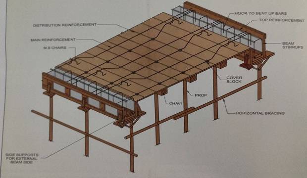
(d) PROCEDURE FOR SLAB REINFORCEMENT
- Take the measurement of the cutting length of the slab reinforcement and accordingly the cutting can be done.
- For continuous slabs, consider the projection of the bent-up bars in the adjacent slab while calculating the cutting lengths of the slabs.
- The cut bars should be stored in bunches slab-wise and can be transferred on the slabs accordingly.
- Marking for the c/c distance of the bars should be done on the slab plates with the help of chalk.
- Lay the main reinforcement as per the marking.
- Place the distribution steel on the main reinforcement and every junction should be tied with binding wire.
- Bent-up bars should be bent at the required length from support as per the type of slab, i.e. continuous or simply supported, etc.
- Place the chairs under every bent-up bar to maintain the top reinforcement at the top.
- Bent-up should be lifted considering the slab cover and slab thickness.
- All hidden beams should be placed such that the center of the hidden beam should be considered the center of the proposed wall on that beam.
- The ring of the hidden beam should be bound such that it is just 1″ (25mm) less than the thickness of the slab. e.g. for 5″ (125mm) thick slab, the ring for H.B. should be 4″ (100mm) in height.
(e) PROCEDURE FOR WATER TANK REINFORCEMENT
- For the water tank, reinforcement of the bottom slab, along with the beams, should be placed and bound properly.
- Through this slab reinforcement of vertical pardi (R.C.C. thin wall) should be taken with necessary anchorage. Vertical bars of the pardi are normally erected first.
- Provide Chamber bars at the corner as per the design.
- Generally, double jali is provided to the bottom slab.
- After the casting of the bottom slab, horizontal reinforcement of the vertical pardi should be bound with due care, on anchorage inside the pardi.
- Provide horizontal reinforcement at both the faces of Pardi. Ensure a proper cover to this reinforcement. Side chamber bars to be provided as per the specified spacing.
- After casting off the side Pardi, the formwork of the top slab should be bound as per the design.
- Provide a manhole for the top slab along with a vent pipe hole. For the manhole, extra bars should be provided along the periphery of the opening.
- If cut pieces are to be used for the top slab, the lap length of the same should be 69D, where D is the diameter of the bar. Care should be taken to provide laps in a staggered manner.
- For chajjas and cantilever slabs, the main reinforcement should be provided at the top of the slab.
- Every alternate bar or as specified by the R.C.C. designer should be bent back at the bottom.
- The anchorage of the top reinforcement should be provided either in the beam, adjacent slab, or column, as the case may be.
- For beams and lintels, the reinforcement should be anchored around the beam with the required anchorage.
- For slabs, the reinforcement should be continued in the adjacent panels for the required anchorage length.
- The anchorage length should be a minimum 69D or the span of the cantilever, whichever is more.
- Chairs should be provided below every bar of the slab, to keep the top reinforcement in position.
- Distribution bais should be provided as per the required spacing.
 |
| reinforcement details for chajja |
NEGLIGENCE IN FOOTING JALI
- The spacing of bars differs.
- Each alternate junction of bars is tied with binding wire.
- The column base is not tied to the footing jali properly.
- Column main corner bars are not laid in a 45° position with the plan.
NEGLIGENCE IN COLUMN REINFORCEMENT
- Stirrups for main reinforcement are not bound to each bar.
- Spacing between the stirrups is found to be unequal.
- The main reinforcing bars and stirrups are not tied tightly to each other.
NEGLIGENCE IN BEAM REINFORCEMENT
- The top bars of beams are not bent in 90 degrees. The distance of bent-up from the face of the support differs.
- The spacing of stirrups differs with the specified drawings.
- For the end support of beam, bent-up bars are not bent into the beam or column up to the required depth.
- For 150mm wide beams, the pin is not provided to the bottom bars when the number of bars exceeds two.
- Side face reinforcement is not provided to the beams having a depth of more than 750mm.
- Beam bars are not passing through column reinforcement.
- The full bearing of beam bars is not given on the column.
- The angle of 45° is not maintained for a bent-up bar in a beam.
NEGLIGENCE IN SLAB REINFORCEMENT
- The spacing of the main reinforcement.
- A distance of bent up from the face of the support differs from typical bar bending.
- Every junction of the main and distribution bars is not tied to each other properly.
- For the end support of the slab, bent-up bars are not bent or hooked into the beam.
- Insufficient chairs are provided under the bent-up bars.
- Laps for slabs are not provided in a staggered manner.
- The lap lengths provided are insufficient.
- The length of the projection of bent-up bars, in the case of the continuous slab, is not found as per the requirement, i.e., L/4.
- The height of the bent-up bars is always found to be the same for different thicknesses of slabs.
- The extra length of cutting bars at the ends leads to an improper end cover.
- Insufficient chairs are provided to cantilever slabs, due to which top reinforcement is not properly maintained at the top position.
- Same lap length for all diameters of bars.

CHECKLIST & CERTIFICATE BEFORE CASTING SLAB
- Do not cast: he s.ab before checking is done by the concerned higher authorities.
- The checklist should be written by J.E. & checked by the concerned higher authorities.
- Send one copy of the checklist to the head office after the necessary checking.
- Refer to the checklist as a guideline for checking work.
MANAGEMENT BEFORE AND AT THE TIME OF SLAB CASTING
- Sieve analysis of the sand and metal should be carried out to decide the volumetric mix design.
- According to the importance of the structural member, the method of mixing, i.e., volumetric by weight should be decided.
- Levels of the slabs and their dimensions should be checked, well in advance.
- Slabs should be checked by the architect and R.C.C. consultants for the correctness of dimensions and reinforcement.
- The concealed electric conduit work should be checked for its quality as per the requirements.
- Arrangements for water and standby arrangements for the same should be made.
- A sufficient number of laborers should be present for concreting.
- The contractor should be informed of the time of commencing the slab and the maximum time allowed for slab casting, well in advance.
- Decide the position of the reinforced cement concrete joints for a large slab with the prior consent of the R.C.C. consultant.
- Check all the machines for proper operation.
- Check the availability of fuel for the machines such as mixers, vibrators, lifts, etc.
- Check whether a sufficient number of measuring boxes (farmers) are ready or not.
- Check a sufficient number of cube moulds for casting the cubes for checking.
- Ensure the removal of wooden pieces, papers, dust, etc. from the slab and beam before casting.
- Check the arrangement of planks and M.S. walkways over the slab, for easy labour movement; without disturbing concrete & reinforcement.
- Ensure sufficient light arrangement for late-night concreting.
- Ensure for the arrangement of staff & allot their duties.
- Check that all the fan hook boxes are placed in position.
- Check whether the vibrator is properly placed over the stand for use during concreting.
- Ensure that one supervisor is present near the mixer for checking proper mixing and the correct quantity of water for mixing the concrete. This supervisor should maintain the register batch-wise and control the proportion of the ingredients. The slump cone & cube moulds must be available with the supervisor.
- Check whether the M.S. platform is placed over the slab, for delivery of the reinforced cement concrete on the platform.
- Buttering of the mixer should be done before starting the regular slab work.
- Quality and consistency of the concrete mix is checked for the first batch and alterations, if any, should be made in the mix proportion as per the ingredients available.
- Care should be taken first to cast the beams and compact layer-wise with the help of the vibrator. Though the vibrator is applied to beams, reinforced cement concrete should be also compacted manually with the help of tamping rods.
 |
| checklist & Certificate before casting slab |
- For the initial batch, the slump test should be carried out to find out the consistency and workability of the concrete mix. The alterations in the proportion of ingredients should be made if the mix is not consistent and workable.
- “Beams first and then slabs’: This method should be applied for concreting.
- Ensure the proper level of the slab after finishing by the mason, by visual inspection.
- Ensure proper thickness and finishing of staircase steps and waste slab.
- Do not allow anyone to walk over fresh and finished concrete.
- Ensure the presence of a carpenter below the slab shuttering, during casting, is in progress.
- Ensure a proper bottom and side cover for slabs and beams at every stage of concrete.
- Ensure a proper finish to the slab panel, where the lift delivers the concrete.
- For concreting in hot weather conditions, cover the fresh slab by wet gunny bags, to prevent drying of the top surface of the reinforced cement concrete.
- In case of rain, cover the slab with a big plastic turpentine sheet to protect it.
Bar bending schedule for beam – click here for download
Bar bending schedule for the column – click here for download
Bar bending schedule for slab – click here for download
Bar bending schedule for footing – click here for download
1. Why concrete is used in RCC?
Reinforced Cement Concrete is a combination of concrete and steel to build good structures instead of using only concrete. Its life 100 years or more than, not any effect taking high temperature.
2. What are the types of reinforced concrete?
Glass Fiber Reinforced Concrete (GFRC)
Steel Fiber Reinforced Concrete (SFRC)
Natural fiber reinforced concrete (NFRC)
Polypropylene Fiber Reinforced concrete (PFR)
3. How many kg of steel is required in 1m3 of concrete?
Generally, 100-125 kg stell required 1m3 concrete.
4. Why steel is used in RCC?
When steel mix with concrete its life is 100 years & stell can stand high temperatures. & it’s very flexible.
Nice information complete details given of reinforcement cement concreat